
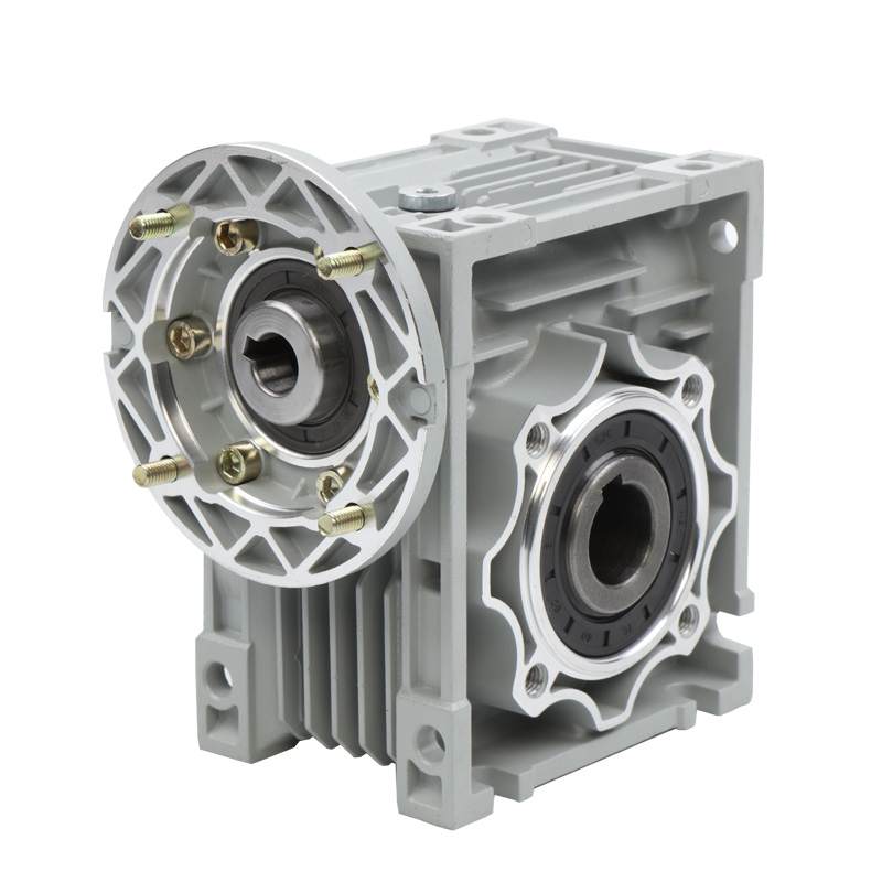
Что такое фланец двигателя? The Complete Engineering Guide to B5, B14 & NEMA C-Face Mounts
Быстрый ответ
A motor flange is the machined, disc-shaped mounting face on the drive end of an electric motor that lets it bolt directly and coaxially to a pump, коробка передач, or other driven machine — with no separate base or coupling alignment. The flange has a precision spigot (also called a pilot or register) that centers the motor, and a ring of mounting holes on a defined pitch circle diameter (PCD). International standard МЭК 60034-7 defines flange mounts with IM codes such as IM B5 (large flange, clearance/through holes = FF type) а также IM B14 (small flange, tapped/threaded holes = FT type); dimensions come from МЭК 60072. In North America the equivalent concepts are the NEMA C-face (threaded holes) а также D-flange (through holes) defined in НЕТ МГ 1. Choosing the wrong flange type is the single most common motor ordering error.
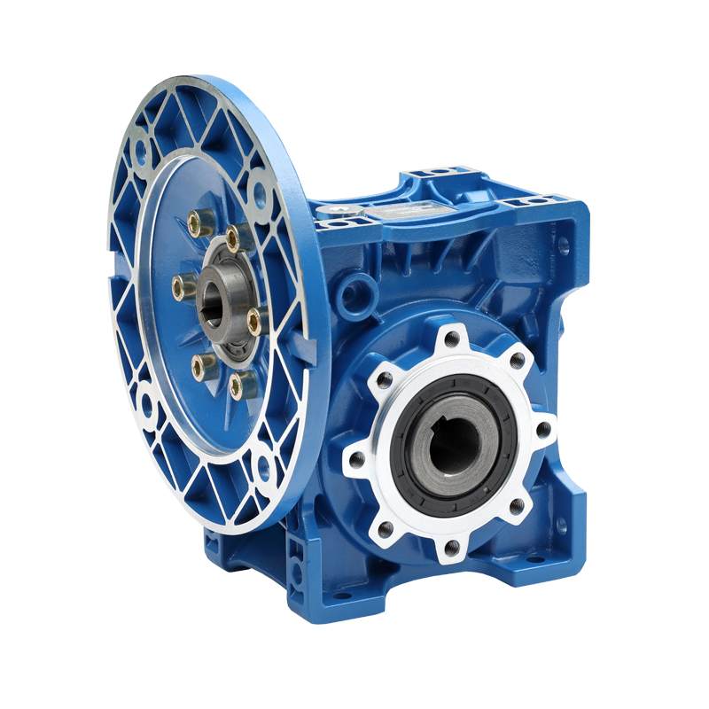
Что такое фланец двигателя? (Определение)
А motor flange is a flat, machined ring or plate on the drive end (DE) of a motor that replaces — or supplements — the traditional mounting feet. Instead of resting on a base, a flange-mounted motor is fastened face-to-face onto the driven equipment. Because the flange and its spigot are machined in the same operation as the bearing housing, the motor shaft ends up automatically concentric with the mating bore, so no field alignment is needed.
Every motor flange is built from three functional features, and understanding them is the key to specifying the correct part:
1. The spigot (pilot / register / rabbet)
The spigot is a short cylindrical shoulder machined concentric to the shaft. It slots into a matching recess in the gearbox or pump housing and does the actual centering work — the bolts only clamp. IEC calls it the spigot or pilot; NEMA calls it the rabbet or register (измерение AK). Its concentricity to the shaft is tightly toleranced under МЭК 60072-1.
2. The mounting holes and pitch circle diameter (PCD)
The bolt holes sit on a pitch circle diameter (PCD), also called the bolt circle diameter (BCD) or NEMA AJ. The holes are either clearance (through) holes — you pass a bolt through the flange into a tapped machine housing (МЭК FF / ЗДЕСЬ НЕТ D-flange) — or tapped (threaded) holes — you screw a bolt from the machine side into the motor face (МЭК FT / ЗДЕСЬ НЕТ C-face).
3. The flange outer diameter and thickness
These set the envelope and the load path. On a large FF/B5 flange the outer diameter is bigger than the motor body; on a small FT/B14 flange it is usually equal to or smaller than the body. The flange must carry the full cantilevered weight and torque reaction of the motor, so its thickness is a structural, not cosmetic, измерение.

How a Flange Mount Works: Шаг за шагом
- The spigot enters the housing bore. The machined pilot diameter is a close (often h7/H8) slip fit into the mating recess of the gearbox, pump adapter, or bracket. This locates the motor radially and forces the shaft axis to coincide with the driven-shaft axis.
- The faces seat flat. The machined flange face contacts the machine face squarely, setting axial position and squareness (perpendicularity of the shaft to the mounting plane).
- The coupling engages. Because the shaft is now pre-aligned by the spigot, a rigid or short flexible coupling — or a direct splined/keyed input into a gearbox — can be joined without dial-indicator alignment.
- The bolts clamp. Bolts on the PCD are torqued to develop a clamp load that resists the motor’s weight and the reaction torque. Clamp force, not friction from a loose fit, keeps the joint rigid: F = T / (K·d), where T is bolt torque, d bolt diameter, and K the nut factor (~0.2 for dry steel).
- Load transfers through the flange. Weight and vibration flow from the motor, through the flange ring, into the machine structure — which is why flange concentricity and stiffness directly affect bearing life and vibration.
The result is a compact, self-aligning, floor-space-free drive. That is exactly why close-coupled pumps, speed reducers, and OEM machines overwhelmingly use flange motors instead of foot-mounted ones.
Motor Flange Types Compared (МЭК 60034-7)
МЭК 60034-7 assigns each mounting arrangement an Я (International Mounting) code. The four flange-related codes below cover almost every industrial flange motor. The most important — and most confused — distinction is B5 vs. B14: B5 has clearance holes (bolt passes through the flange), while B14 has tapped holes (bolt threads into the flange).
| Code | IM number | Flange type | Hole type | Flange vs. body OD | Typical use |
|---|---|---|---|---|---|
| В5 | Я 3001 (IM B5) | Large flange (FF) | Clearance / through | Larger than body | Насосы, коробки передач, редукторы, agitators |
| B14 | Я 3601 (IM B14) | Small face flange (FT) | Tapped / threaded | Equal or smaller | Маленькие насосы, Станки, compact drives |
| B35 | Я 2001 (IM B35) | Ступня + large flange | Clearance (FF) + feet | Larger than body | Heavy reducers, высокий крутящий момент, retrofits |
| B34 | Я 2101 (IM B34) | Ступня + face flange | Tapped (FT) + feet | Equal or smaller | Belt drive + face mount combo, ОЕМ |
Vertical variants (shaft down = V1, shaft up = V3/V18) use the same flanges but need thrust-rated bearings and, outdoors, a rain canopy. For a foot-mounted comparison, see our guide to AC против. двигатели постоянного тока.

IEC Flange vs. NEMA Flange (Global Sourcing)
North American equipment uses NEMA MG 1 terminology instead of IM codes. Functionally they map cleanly, but the dimensions and frame numbers differ, so an IEC B5 motor will нет bolt to a NEMA D-flange housing without an adapter.
| Особенность | МЭК (60034-7 / 60072) | ЗДЕСЬ НЕТ (MG 1) |
|---|---|---|
| Tapped-hole flange | FT flange = B14 | C-face (например. 56С, 143TC) |
| Through-hole flange | FF flange = В5 | D-flange (например. 56Д, 254TD) |
| Centering feature | Spigot / pilot / register | Rabbet / register (dim AK) |
| Bolt circle | Pitch circle diameter (PCD) | Bolt circle (dim AJ) |
| Flange OD | Flange outer diameter | Измерение BD |
| Size unit | Millimetres | Inches |
| Dimensional standard | МЭК 60072-1 | НЕТ МГ 1 / МЭК 60072 |
FF and FT Flange Designations Explained
Under IEC 60072-1, a flange is named by its type letters plus the pitch circle diameter in millimetres. Так FF265 means a through-hole (FF) flange with a 265 mm PCD; FT115 means a tapped (FT) flange with a 115 mm PCD. The table pairs common IEC frame sizes with their standard flange.
| IEC frame | Std. B5 flange (FF) | PCD (мм) | Spigot Ø N (мм) | Std. B14 flange (FT) |
|---|---|---|---|---|
| 63 | FF115 | 115 | 95 | FT75 |
| 71 | FF130 | 130 | 110 | FT85 |
| 80 | FF165 | 165 | 130 | FT100 |
| 90 | FF165 | 165 | 130 | FT115 |
| 100 / 112 | FF215 | 215 | 180 | FT130 |
| 132 | FF265 | 265 | 230 | FT165 |
| 160 | FF300 | 300 | 250 | FT215 |
| 180 | FF300 | 300 | 250 | — |
| 200 | FF350 | 350 | 300 | — |
Spigot diameter “Н” is the pilot register the housing bore must match. Values follow IEC 60072-1; always confirm against the specific manufacturer datasheet before machining a mating part.
Motor Flange Engineering Data: Tolerances, Loads & Формулы
A flange looks simple, but its performance is governed by tight geometric tolerances and a real mechanical load path. Getting these numbers right is what separates a vibration-free drive from premature bearing failure.
Concentricity and run-out tolerances (МЭК 60072-1)
МЭК 60072-1 defines two tolerance grades for the spigot and face: Normal (Н) а также Reduced (р) for precision applications. The spigot must be concentric to the shaft, and the mounting face perpendicular to it, within these limits (total indicator reading, TIR):
| Spigot Ø N (мм) | Concentricity — Normal (мм) | Concentricity — Reduced (мм) | Face perpendicularity — Normal (мм) |
|---|---|---|---|
| ≤ 250 | 0.10 | 0.05 | 0.10 |
| > 250 к 500 | 0.125 | 0.063 | 0.125 |
| > 500 к 800 | 0.16 | 0.08 | 0.16 |
Exceed these and the shaft runs eccentric to the driven bore, injecting a once-per-revolution radial force that shortens bearing L10 life and raises vibration.
Key formulas for flange-mounted drives
- Bolt clamp load: F = T / (K · d) — clamp force F from torque T, bolt diameter d, nut factor K (≈0.20 dry, ≈0.15 lubricated). Under-torqued flange bolts let the joint fret and loosen under vibration.
- Reaction torque on the flange: T = P × 9550 / не (Н·м), with power P in kW and speed n in rpm. This is the torque the flange bolt pattern must react at start-up and stall.
- Bolt shear from reaction torque: Фbolt = 2T / (неб · PCD) — tangential load per bolt, with nб bolts on the pitch circle diameter. Larger PCD = lower per-bolt load.
- Cantilever bending on the flange: M = W · Lcg — motor weight W acting at its center-of-gravity distance Lcg from the flange face; the reason large motors prefer B35 (foot + фланец) over B5 alone.
- Bearing L10 life: L10h = (10⁶ / 60не) · (К/П)³ for ball bearings — misalignment from a poor flange fit raises the equivalent load P and cuts life cubically (see SKF bearing calculator).
Worked example
А 7.5 кВт, 1,450 rpm B5 motor on an FF265 flange (PCD 265 мм, 4 bolts): reaction torque Т = 7.5 × 9550 / 1450 ≈ 49 Н·м. Tangential load per bolt Фbolt = 2 × 49 / (4 × 0.265) ≈ 92 Н — small, so the bolts are sized by clamp/vibration, not shear. This confirms why correct preload torque matters more than bolt count on most flange motors.
Materials and typical thermal limits
Flanges are cast iron (heavy-duty rigidity), алюминий (light OEM frames), or fabricated/stainless steel (промываясь). Insulation class governs the surface heat the flange transmits into the driven machine: Класс Б 130 °С, Класс F 155 °С, Класс Н 180 °С per МЭК 60034-1 — relevant when a plastic pump adapter meets a hot motor flange.
Best Applications for Flange-Mounted Motors
| Заявление | Preferred flange | Почему |
|---|---|---|
| Close-coupled centrifugal pumps | В5 / D-flange | Direct axial coupling, self-aligning, no baseplate |
| Gearboxes & speed reducers | В5 / B14 | Motor bolts straight to reducer input bell — see our коробка передач гид |
| Compact machine tools & текстильные машины | B14 / C-face | Small footprint, tapped-hole face fits limited space |
| Миксеры & agitators (вертикальный) | B5 V1 | Shaft-down flange mount with thrust bearing |
| Конвейеры & heavy reducers | B35 (foot + фланец) | Flange aligns, feet carry weight & вибрация |
| OEM pump/gear assemblies | B14 / C-face | Standardised pilot for modular, interchangeable builds |
How to Select the Right Motor Flange: Шаг за шагом
- Confirm the standard. МЭК (metric, IM codes) or NEMA (inch, C/D-face)? This is set by your existing machine, not preference.
- Read the mating housing. Measure the recess bore (this must equal the motor spigot Ø N / AK) and the bolt circle (PCD / AJ). These two numbers define the flange.
- Identify the hole type. Do bolts pass through the flange into a tapped housing (В5 / D-flange, FF) or thread into the motor face (B14 / C-face, FT)? This is the #1 mistake — verify with a photo or thread gauge.
- Match the frame & вал. The flange PCD is tied to frame size; also confirm shaft diameter, длина, and key so the coupling fits.
- Check load direction. Heavy motor, вибрация, or overhung load? Step up to B35 (foot + фланец) rather than trusting the flange bolts alone.
- Specify tolerance grade. Precision spindles or high-speed pumps warrant the Reduced (р) concentricity grade, not Normal (Н).
- Select material & enclosure. Cast iron for industrial rigidity, stainless for washdown, aluminium for light OEM; then pick IP/enclosure rating.
Common Engineering Mistakes with Motor Flanges
- Confusing B5 and B14. They look similar but B5 has clearance holes and B14 has tapped holes. A B14 ordered as B5 will not bolt on. This is the most frequent flange ordering error.
- Matching PCD but ignoring the spigot. Two flanges can share a bolt circle yet have different pilot diameters — the motor won’t center. Always match spigot Ø N (AK) а также PCD (AJ).
- Mixing IEC and NEMA. An IEC B5 flange will not fit a NEMA D-flange housing; the metric/inch dimensions differ. Use an adapter plate or order to the correct standard.
- Overloading a bare B5 flange. Using flange-only mounting for a heavy or overhung load overstresses the flange bolts and bends the mounting face. Move up to B35.
- Under-torquing the bolts. Insufficient clamp load lets the joint fret, loosen, and shift under vibration. Torque to spec using F = T/(K·d).
- Forcing a vertical mount. Turning a horizontal B5 motor shaft-down without a thrust-rated bearing (and rain canopy outdoors) leads to early bearing failure.
- Paint or burrs on the spigot/face. Contamination breaks the flat face contact and concentric fit, re-introducing the misalignment the flange was meant to remove.
Motor Flange Troubleshooting Table
| Проблема | Likely cause | Решение |
|---|---|---|
| Motor won’t bolt to housing | Wrong flange type (B5 vs B14) or IEC/NEMA mismatch | Verify hole type & стандартный; use adapter or correct motor |
| Bolts line up but motor won’t seat | Spigot Ø doesn’t match the housing recess | Match pilot register Ø N / AK, not just PCD |
| High vibration after mounting | Spigot concentricity out of tolerance, or burrs/paint on face | Clean & deburr faces; check TIR to IEC 60072-1 grade |
| Recurring bearing failure | Shaft misalignment from poor flange fit; радиальная нагрузка | Re-check spigot fit; add support or switch to B35 |
| Flange bolts keep loosening | Under-torque / no clamp preload; вибрация | Torque to spec, add thread-locker or lock washers |
| Flange face cracked or bent | Overhung/heavy load on flange-only (В5) mount | Upgrade to foot + фланец (B35); check load path |
| Water in motor (vertical mount) | Shaft-up without seal / shaft-down without canopy | Add rain canopy or shaft seal; specify V-mount properly |
| Coupling still needs alignment | Non-precision (Normal) flange used on precision drive | Specify Reduced (р) tolerance grade flange |
Часто задаваемые вопросы
What is a motor flange used for?
A motor flange lets a motor bolt directly and coaxially onto a pump, коробка передач, or machine without a separate base or dial-indicator alignment. The machined spigot centers the shaft automatically, saving floor space and installation time.
What is the difference between a B5 and B14 flange?
A B5 flange is large, has clearance (through) holes, and its outer diameter is bigger than the motor body — the bolt passes through the flange into the machine. A B14 flange is smaller, has tapped (threaded) holes on the face, and the bolt threads into the motor. Confusing the two is the most common ordering error.
What is the spigot (register) on a motor flange?
The spigot — also called the pilot, register, or NEMA rabbet — is a precision machined shoulder concentric to the shaft. It fits into a matching bore in the driven equipment and does the actual centering; the bolts only clamp. Its diameter must match the housing exactly.
Are IEC and NEMA flanges interchangeable?
Нет. IEC flanges (B5/B14, metric, IM codes) and NEMA flanges (D-flange/C-face, inch) use different dimensions and frame numbering. An IEC motor will not bolt to a NEMA housing without an adapter plate, even if the concepts are equivalent.
What does FF265 or FT115 mean?
Under IEC 60072-1 the number is the pitch circle diameter in millimetres. FF265 is a through-hole flange with a 265 mm PCD; FT115 is a tapped-hole flange with a 115 mm PCD. The letters give the hole type (FF = clearance, FT = tapped).
When should I use B35 instead of B5?
Use B35 (foot + фланец) when the motor is heavy, carries an overhung load, or is subject to strong vibration. The feet carry the weight and damp vibration while the flange still aligns the drive — reducing stress on the flange bolts and face.
Why Choose Greensky for Flange-Mounted Motors?
С 2011, Грински Пауэр has engineered BLDC двигатели, щеточные двигатели постоянного тока, шаговые двигатели, а также коробки передач with correctly machined flanges for OEM customers in over 50 страны. When the mounting interface has to be right the first time, our engineers spec the flange with you — spigot, PCD, tolerance grade, and standard.
- Both standards: IEC B5/B14/B35 and NEMA C-face / D-flange, plus custom pilot diameters.
- Precision machining: spigot concentricity and face perpendicularity held to IEC 60072-1 grades.
- Integrated drives: двигатель + gearbox supplied as a matched flange assembly — no adapter guesswork.
- 100% тестирование: every unit run-tested; run-out and vibration verified.
- Соответствие стандартам: designed to IEC 60034 / НЕТ МГ 1 practice; ИСО, CE certified.
- OEM/ODM support: full engineering help through United Motion Inc. в Северной Америке & Европа.
Ссылки
- МЭК 60034-7, Rotating electrical machines — Classification of types of construction, mounting arrangements and terminal box position (IM code). https://webstore.iec.ch/publication/2765
- МЭК 60072-1, Dimensions and output series for rotating electrical machines — Frame numbers 56 к 400 and flange numbers 55 к 1080. https://webstore.iec.ch/publication/351
- МЭК 60034-1, Вращающиеся электрические машины. Номинал и производительность. https://webstore.iec.ch/publication/60034-1
- НЕТ МГ 1, Двигатели и Генераторы (C-face, D-flange, AJ/AK dimensions). https://www.nema.org/standards/view/motors-and-generators
- НЕТ МГ 1-2009 (full text, law.resource.org). https://law.resource.org/pub/us/cfr/ibr/005/nema.mg-1.2009.pdf
- АББ, Low voltage motors — Mounting arrangements and IM codes (technical guide). https://new.abb.com/motors-generators/iec-low-voltage-motors
- Сименс, SIMOTICS General Purpose Motors — Types of construction / монтаж. https://www.siemens.com/global/en/products/drives/electric-motors.html
- СКФ, Bearing rating life (Л10) and mounting/alignment guidance. https://www.skf.com/group/support/engineering-tools/bearing-calculator
- IEEE Standard 112, Test Procedure for Polyphase Induction Motors and Generators. https://standards.ieee.org/ieee/112/4703/
- НАС. Министерство энергетики, Motor Systems — Energy Conservation Program (10 Часть CFR 431). https://www.energy.gov/eere/motors