
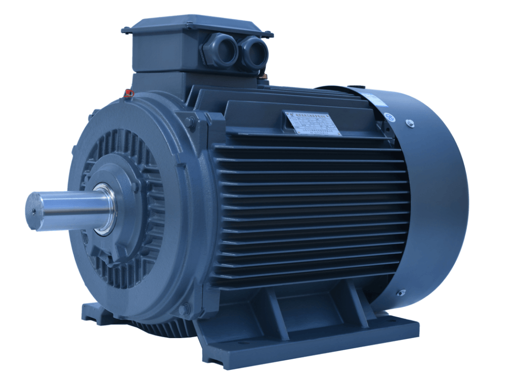
Three Phase Asynchronous Motor Common Faults & Treatment Methods
What Is a Three-Phase Asynchronous Motor?
A three-phase asynchronous motor — almost always called an inductie motor in North America — is a rotating machine that converts three-phase AC electrical power into mechanical torque. “Asynchronous” means the rotor never reaches the speed of the rotating stator field: it always runs slightly slower, and that speed deficit (de uitglijden) is exactly what induces current in the rotor and produces torque. It is the workhorse of industry — induction motors consume roughly 70% of all industrial electricity (ONS. DOE / IEC estimates), which is why their failure modes and treatment methods matter to every maintenance program.
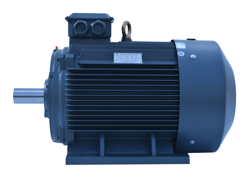
Key Construction Types
| Construction | Rotor type | Typisch gebruik | Service notes |
|---|---|---|---|
| Squirrel-cage (TEFC / ODP) | Cast aluminium or copper bars shorted by end rings | Pompen, fans, transportbanden, compressoren | Most common; rugged, no slip rings |
| Wound-rotor (slip-ring) | 3-phase winding + external resistors via slip rings | Kranen, mills, high-inertia starts | Adjustable start torque; brush/slip-ring wear |
| Line-start PM (synRM/PMSM) | Permanent-magnet or reluctance rotor | IE4/IE5 premium efficiency | Hogere efficiëntie; needs drive or special design |
How a Three-Phase Asynchronous Motor Works
The principle is electromagnetic induction — no brushes, no external excitation on the rotor. The sequence is:
- Three-phase supply creates a rotating field. The 120°-spaced stator windings fed by 120°-spaced voltages produce a magnetic field that rotates at the synchrone snelheid NS = 120·f / P (f = supply frequency, P = pole count).
- The rotor lags behind (uitglijden). A stationary rotor would see a changing field and a large induced current, but as it speeds up the relative motion shrinks. At exactly NS there would be zero relative motion, zero induced rotor current, and zero torque — so the rotor settles just below NS.
- Rotor current is induced by slip. The slip frequency is fR = s·f (s = slip fraction). Bij 3% slip on 50 Hz, the rotor bars carry current at 1.5 Hz — enough to make torque, small enough to keep losses low.
- Torque balances the load. Torque rises with slip in the stable region; the motor finds the slip where electromagnetic torque equals the load torque. More load → more slip → more rotor current → more torque, up to the breakdown point.
- Losses become heat. Copper loss (I²R) in stator and rotor, iron loss in the core, and friction/windage all raise temperature. That is why thermal class and cooling are central to fault treatment.

Synchrone snelheid & Slip — Reference Table
| Polen (P) | NS @ 50 Hz (toerental) | NS @ 60 Hz (toerental) | Typical full-load slip |
|---|---|---|---|
| 2 | 3000 | 3600 | 3–6% |
| 4 | 1500 | 1800 | 2–5% |
| 6 | 1000 | 1200 | 1.5–4% |
| 8 | 750 | 900 | 1–3% |
Worked example. A 4-pole, 50 Hz motor with a nameplate speed of 1455 toerental: NS = 120 × 50 / 4 = 1500 toerental, slip s = (1500 - 1455) / 1500 = 3.0%, and the rotor current frequency is fR = 0.03 × 50 = 1.5 Hz. If slip climbs well above the nameplate value under the same load, suspect overload or broken rotor bars.
The Most Common Faults — and Where They Come From
Field data from industrial maintenance programs consistently shows a similar breakdown. Treat these percentages as a prioritization tool, not a precise census:
| Fault category | Share of failures* | Typical root cause | First symptom |
|---|---|---|---|
| Isolatie van de statorwikkeling | ~32% | overheat, voltage unbalance, vocht, besmetting | ground fault, trip, burning smell |
| Handelswijze / mechanisch | ~30% | smering, verkeerde uitlijning, besmetting | lawaai, trillingen, hot bearing |
| Rotor (bars / rings) | ~14% | thermal cycling, start surge, casting defect | current swing, low torque, warmte |
| Supply / controle | ~14% | single-phasing, contactor, wrong connection | won’t start, hum, reverse |
| Other (environment, laden) | ~10% | blocked cooling, overbelasting, koppelen | overheat, trillingen |
*Aggregated from multiple motor-reliability surveys (bijv. IEEE/EPRI-style maintenance studies). Exact shares vary by industry and duty.
Diagnostic Decision Table — Symptom → Subsystem → First Test
| Observed symptom | Likely subsystem | First check (external → mech → elec) |
|---|---|---|
| Won’t start, no hum | Supply / controle | Voltage at terminals, fuses, contactor, OLR setting |
| Won’t start, loud hum | Supply (single-phase) / mechanical lock | Phase balance; manually rotate load (barring) |
| Starts but trips immediately | Electrical fault / overbelasting | Megger to ground; verify OLR vs nameplate |
| Runs slow under load | Supply / rotor | Spanning & balance; broken-bar test (MCSA) |
| Oververhitting | Thermisch (all) | Load current vs FLA; cooling path; voltage balance |
| Trillingen / lawaai | Mechanisch | Handelswijze, uitlijning, balance; then electrical spectrum |
| Shell/case live | Insulation ground | Megger phase-to-frame; dry or rewind |
Engineering Data You Need for Diagnosis
Core Formulas
| Hoeveelheid | Formule | Opmerkingen |
|---|---|---|
| Synchronous speed | NS = 120·f / P | f in Hz, P = poles |
| Slip (fraction) | s = (NS − NR) / NS | NR = actual rotor speed |
| Slip frequency | FR = s·f | Frequency induced in rotor bars |
| Shaft torque | T = 9550·PkW / Ntoerental | Also T = 9.549·P / N |
| Voltage unbalance (ER IS GEEN) | %UB = max deviation from avg ÷ avg × 100 | ≤1% continuous; >5% not advised |
| Current unbalance (rule) | ≈ 6–10× voltage unbalance | Negative-sequence heating |
| Nominale stroom | I = P / (√3 · V · cosφ · η) | 3-phase apparent-power relation |
| Bearing life (L10u) | L10u = (C/P)P · 106 / (60·n) | p= 3 bal, 10/3 rol |
Worked Example — Torque and Unbalance
A 7.5 kW, 4-pool, 50 Hz motor nameplated at 1455 toerental en 400 V:
- Nominaal koppel: T = 9550 × 7.5 / 1455 = 49.2 N·m.
- Slip: s = (1500 - 1455)/1500 = 3.0% (matches the stable region).
- Voltage unbalance check: measured line voltages 400 V / 408 V / 392 V → average 400 V, max deviation 8 V → 2.0% unbalance. Per NEMA MG 1 this already calls for ~5% load derating, and implies roughly 12–20% current unbalance — a real overheating risk worth correcting.
IEC 60034-30-1 Efficiëntieklassen (D.W.Z)
| Klas | Relative efficiency | Regulatory status (typisch) |
|---|---|---|
| IE1 | Standaard (lowest) | Phasing out / banned for new in US & EU |
| IE2 | Hoog | Legacy minimum in some regions |
| IE3 | Premie | Current U.S. & EU minimum for most ratings |
| IE4 | Super-premium | Growing adoption |
| IE5 | Ultra-premium | Line-start PM / synRM emerging |
Isolatietemperatuurlimieten (IEC 60034-1 / GEEN MG 1)
| Klas | Max winding temp (° C) | NEMA temp rise @ 40 °C amb | Practice |
|---|---|---|---|
| B | 130 | 80 °C rise (total 120 ° C) | Basislijn |
| F | 155 | 105 °C rise (total 145 ° C) | Used as insulation, run at Class B rise |
| H | 180 | 125 °C rise (total 165 ° C) | High-duty / high-ambient |
De 10 °C rule: elk 10 °C of sustained temperature above the design point roughly halves insulation life. A motor that runs hot is not just inefficient — it is on a timer. This is why “overheating” sits at the top of any treatment list.
Isolatie testen (IEEE 43-2013)
| Metric | Criterium | Action |
|---|---|---|
| Minimum insulation resistance | ≥ 1 MΩ + 1 MΩ per kV rated (bijv. 400 V → ≥ 1.4 MΩ) | Below → dry / clean / reparatie |
| Polarization Index (PI = R10min/R1min) | > 2.0 Goed; 1.5–2.0 questionable; < 1.0 dangerous | <1.0 → do not operate |
| Test voltage | 500 V DC for ≤1 kV windings (bijv. 400 V motor) | Use megger, lockout/tagout first |
A healthy 400 V winding reads well above 1.4 MΩ with PI > 2. A reading near or below the minimum, or a PI under 1.0, means moisture, besmetting, or insulation breakdown — the leading cause of the “won’t start / trips / burns” cluster.
Best Applications & Where Faults Cluster
| Sollicitatie | Why induction motors fit | Top fault to watch |
|---|---|---|
| Pompen & compressoren | Continuous duty, constante snelheid | Slijtage van lagers, single-phasing |
| Fans & blazers | High inertia, eenvoudige bediening | Blocked cooling → overheat |
| Transportbanden & materiaalbehandeling | Robust, reversible | Verkeerde uitlijning, overbelasting |
| Brekers / mixers (high inertia) | High starting torque designs | Rotor-bar stress, overheating |
| Werktuigmachines | Stable speed | Vibration from imbalance |
| HVAC & building systems | Weinig onderhoud | Contamination, moisture ingress |
Stap voor stap: Selecting & Maintaining for Reliability
Most “common faults” are actually maintenance gaps. A short, repeatable program prevents the majority of failures:
- Size to the load, not the catalog. Match torque (T = 9550·P/n) and duty cycle; over-sizing wastes energy, under-sizing overheats.
- Verify the supply before commissioning. Confirm 3-phase voltage balance ≤1% (GEEN MG 1), correct tap/connection (Δ vs Y), and proper phase rotation.
- Choose the thermal class for the environment. Use Class F insulation run at Class B rise for margin; specify Class H for high ambient or frequent starts.
- Baseline the insulation. Record IR and PI per IEEE 43 when new or after rewind — every future test is compared to this trend, not an absolute number.
- Baseline vibration. Capture the as-new spectrum; rising overall levels or new sidebands at 2×slip frequency flag broken rotor bars early.
- Grease on schedule. Fill to ~1/3–2/3 of the bearing cavity; over- or under-greasing is itself a leading cause of bearing failure.
- Keep it cool and clean. A 1-inch dust coat on TEFC fins can raise winding temperature 20 °C — clean the frame and check the fan.
Veel voorkomende technische fouten
| Fout | Why it bites | Better practice |
|---|---|---|
| Ignoring 1–2% voltage unbalance | Creates 6–10× current unbalance and silent overheating | Correct supply; derate per NEMA MG 1 above 1% |
| Replacing a motor without checking the load | Same fault recurs in weeks | Bar the load, check coupling/alignment first |
| Over-greasing bearings | Seal damage, churning heat | Fill 1/3–2/3 cavity on a schedule |
| Swapping any two leads “to reverse” on a running VFD | Can trip or damage drive | Reverse at the drive, not the terminal box |
| Judging health by frame temperature alone | Winding runs much hotter than the frame | Use RTD/thermistor or megger + trend |
| Skipping the PI test, reading only spot IR | Misses moisture/contamination trends | Run full 10-min IEEE 43 test |
Tabel voor probleemoplossing: Probleem → Oorzaak → Oplossing
| Probleem | Waarschijnlijke oorzaak | Behandeling |
|---|---|---|
| Motor does not start, no hum | No supply / open fuse / OLR tripped / control fault | Check voltage at terminals, fuses, contactor, OLR setting; restore supply |
| Motor hums but will not turn | Single-phasing, mechanical lock, wrong Δ/Y connection | Measure 3-phase balance; bar the load; correct connection per nameplate |
| Trips immediately on start | Short circuit, ground fault, overbelasting, wrong OLR | Megger to ground; verify OLR vs nameplate; free the load |
| Runs slow under load | Low voltage, single-phase under load, broken rotor bars | Measure terminal voltage/balance; broken-bar (MCSA) test; rewind rotor |
| Oververhitting / trips on thermal | Overbelasten, blocked cooling, voltage unbalance, winding fault | Check load current vs FLA; clean cooling path; correct unbalance; megger |
| Excessive vibration / lawaai | Slijtage van lagers, verkeerde uitlijning, imbalance, loose feet | Replace/regrease bearing; align coupling; balance rotor; tighten foundation |
| Bearing runs hot | Wrong/little/contaminated grease, fit too tight/loose | Clean, refill 1/3–2/3; replace bearing; correct fit tolerance |
| Shell/case electrically live | Winding ground fault, vocht, damaged lead | Megger phase-to-frame; droog, reparatie, or rewind; fix lead insulation |
| Current swings / unstable | Broken or loose rotor bars (squirrel-cage) | Confirm with MCSA sidebands; reweld or replace rotor |
| Runs in wrong direction | Two phases swapped (phase rotation) | Swap any two supply leads at the disconnect/starter |
Veelgestelde vragen
What are the most common three-phase asynchronous motor faults?
By share of failures: stator winding insulation breakdown (~32%), bearing/mechanical faults (~30%), and rotor-bar faults (~14%), followed by supply/control problems such as single-phasing. Oververhitting, trillingen, failure to start, and live frame are the visible symptoms of these root causes.
Why is single-phasing so destructive?
When one phase opens, the two remaining windings carry the full three-phase load current. Within seconds the overloaded windings heat dramatically, and the motor may keep “rennen” on two phases while cooking itself. Modern overload relays often catch it, but older contactors or worn connections may not — and NEMA MG 1 limits continuous voltage unbalance to 1% to avoid it.
How do I tell an overheated motor from a warm one?
Frame temperature is not winding temperature — the winding runs far hotter. Use embedded RTDs/thermistors, or compare load current against nameplate FLA. Volgens IEC 60034-1 / GEEN MG 1, Class B/F/H limit total winding temperature to 130/155/180 ° C; sustained operation above the design point follows the 10 °C rule (each 10 °C halves insulation life).
What does a low insulation resistance or PI mean?
Per IEEE 43-2013, minimum insulation resistance is 1 MΩ + 1 MΩ per kV rated (A 400 V motor → ≥1.4 MΩ), and the polarization index (R10min/R1min) should exceed 2. Low or falling values mean moisture, besmetting, or insulation breakdown — the leading cause of ground faults and burns. Dry, clean, or rewind as needed.
Can a three-phase motor run missing one phase?
It should not. A motor already running may continue on two phases but will overheat quickly; a motor at rest usually just hums and will not accelerate. Treat any single-phase condition as a fault to clear before restarting.
How often should I test motor insulation?
Baseline at commissioning and after every rewind, then on a scheduled program (commonly annually for critical motors, or tied to predictive-maintenance rounds). Trend the PI over time — a dropping trend matters more than any single reading.
Why Choose Greensky for Three-Phase Motors?
When you need a replacement or a new design built to spec, Greensky supplies a full three-phase asynchronous (induction) motor range — plus BLDC, PMSM, and integrated gear-motor options — engineered to IEC 60034 en NEMAMG 1 so the faults above are designed out, not discovered in the field:
- IE3 / IE4 efficiency: premium-class rotors and lamination stacks that stay cooler and last longer.
- Thermal margin: Class F insulation run at Class B rise, with optional Class H for harsh duty — aligned to the 10 °C life rule.
- Bearing reliability: selected SKF-grade bearings, correct grease fill, and shaft/end-cover fits that resist the #1 failure mode.
- Flens & mounting compatibility: IEC B5/B14 and NEMA C-face — see our motor flange guide.
- Low-MOQ OEM/ODM: custom voltage, enclosure, schacht, and encoder for spares and new machines.
Gerelateerde lectuur
- Synchronous vs Induction Motor: Belangrijkste verschillen
- What Is a DC Motor? Soorten, Principle & Formules
- How to Troubleshoot a DC Motor (Fault Diagnosis)
- AC vs DC Motor: Welke te kiezen
- What Is a Motor Flange? IEC vs NEMA Mounting
- Gearbox vs Gear Motor: Verschillen & Selectie
- Why Robotic Arms Need Speed Reducers
- BLDC Motor Disadvantages Engineers Should Know
Referenties
- IEC 60034-1 — Rotating Electrical Machines: Beoordeling en prestaties (thermische klassen, temperature limits). webstore.iec.ch/publication/67467
- IEC 60034-30-1 — Efficiency Classes (IE1–IE5) for Rotating Electrical Machines. webstore.iec.ch/publication/67784
- GEEN MG 1 — Motors and Generators (veiligheid, thermal rise, voltage-unbalance limits). nema.org/standards/view/mg-1-motors-and-generators
- IEEE 43-2013 — Recommended Practice for Insulation Resistance Testing of Rotating Machinery. standards.ieee.org/ieee/43/4385
- IEEE 112 — Standard Test Procedure for Polyphase Induction Motors (verlies & efficiency methods). standards.ieee.org/ieee/112/4213
- IEEE 841 — IEEE Standard for Petrochemical and Chemical Industry Motors (betrouwbaarheid / onderhoud). standards.ieee.org/ieee/841/5393
- ONS. DOE — Electric Motor Systems Efficiency & Betrouwbaarheid (maintenance guidance). energy.gov/eere/amo/articles/determination-electric-motors
- SKF — Bearing selection, smering & maintenance for electric motors. skf.com/us/products/maintenance-products/bearing-maintenance
- Siemens — Low-voltage motor systems & drive integration. siemens.com/global/en/products/drives.html
- Academic — MCSA / broken-rotor-bar fault diagnosis survey (induction motor condition monitoring). sciencedirect.com — Induction motor fault diagnosis review