
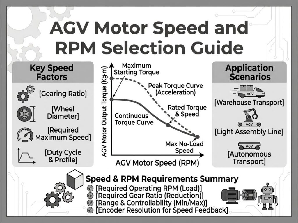
AGV モーターの速度と RPM の選択ガイド: 数式, 規格 & 実用例
Selecting the right motor speed for an Automated Guided Vehicle (無人搬送車) is not a single-parameter decision. It sits at the intersection of vehicle dynamics, gearbox design, battery constraints, and control-loop bandwidth. Get it wrong and you face either a sluggish robot that cannot meet throughput targets, or an over-speeding motor that overheats, wastes battery, and dies prematurely. This guide walks through the full engineering chain—from the fundamental speed-to-velocity formula through IEC 60034-1 duty cycle classification, NEMA MG1 design types, and manufacturer datasheet interpretation—to give you a repeatable workflow for matching motor RPM to any AGV platform.
Why Motor Speed Defines AGV Performance
Motor rated speed (回転数) directly governs three AGV performance pillars:
| Performance Pillar | How Motor Speed Affects It | 不一致の結果 |
|---|---|---|
| Travel Velocity | Wheel speed = motor RPM ÷ gear ratio; vehicle speed = wheel RPM × wheel circumference | Motor too slow → AGV cannot meet cycle-time targets; motor too fast → excessive gear ratio needed, efficiency drops |
| トルク密度 | For a given power, higher-speed motors are smaller and lighter but produce less torque per amp | Undersized torque → stall on ramps, sluggish acceleration; oversized motor → wasted payload capacity and cost |
| Battery Runtime | BLDC motors peak in efficiency at 70–90% of rated RPM; operating far below this wastes energy as heat | Poor efficiency zone → 15–30% shorter battery life per charge cycle, more charging stops, lower fleet OEE |
Industry data from AGV fleet operators shows that motors consistently running below 50% of rated RPM—common in over-geared designs—experience 20–35% higher energy consumption and 40% shorter bearing life compared to motors operating in their optimal efficiency band [1].
簡単な回答: Motor RPM Ranges by AGV Payload Class
For engineering teams that need a fast reference before diving into calculations, the table below consolidates field-proven motor RPM ranges across six AGV payload categories. These values assume BLDC or BLDC servo motors paired with single-stage planetary gearboxes (efficiency ≥ 90%) and polyurethane wheels on epoxy floors.
| Payload Class | Typical AGV Type | Motor Rated RPM | Gear Ratio Range | Wheel RPM (output) | Vehicle Speed | モーター出力 | 電圧 |
|---|---|---|---|---|---|---|---|
| ≤ 100 kg | AGC / Light AMR | 3,000–5,000 | 5:1–10:1 | 300–600 | 0.8–2.0 m/s | 50–100 W | 24V |
| 100–300kg | Warehouse AMR | 3,000–4,000 | 10:1–15:1 | 200–400 | 0.8–1.5 m/s | 100–200 W | 24V / 48V |
| 300–600 kg | Under-Riding AGV | 2,500–3,500 | 8:1–15:1 | 150–350 | 0.5–1.5 m/s | 200–400W | 48V |
| 600–1,200 kg | Towing / Pallet AGV | 2,500–4,000 | 6:1–15:1 | 100–300 | 0.5–1.5 m/s | 400–750W | 48V |
| 1,200–3,000 kg | フォークリフトAGV | 2,000–3,000 | 12:1–25:1 | 80–200 | 0.3–1.0 m/s | 750–1,500 W | 48V / 72V |
| 3,000–20,000 kg | Heavy-Duty AGV | 1,500–2,500 | 15:1–30:1 | 50–120 | 0.2–0.5 m/s | 1.5–5 kW+ | 72V / 80V |
ソース: Consolidated from AGV manufacturer specifications [2][3], gear motor supplier data [4], and GreenSky Power’s AGV motor application guide [5].
The Speed–Torque–Gear Ratio Triangle
Every AGV drive design lives within a three-variable trade space. You cannot optimize one without affecting the other two. Understanding this triangle prevents the most common error in motor speed selection: choosing a motor based on speed alone and discovering the torque is inadequate only during prototype testing.
Variable 1: モーター定格速度 (nN)
The rated speed is the RPM at which the motor delivers its rated torque continuously without exceeding its thermal class limit. For BLDC motors used in AGVs, this typically falls between 1,500 と 5,000 回転数. The rated speed is ない the no-load speed (n0)—the no-load speed is typically 10–20% higher than the rated speed under load [6].
Variable 2: Gearbox Reduction Ratio (私)
The ratio converts motor shaft speed to wheel shaft speed. A higher ratio reduces output speed but multiplies output torque (minus gearbox efficiency losses). For AGV applications, ratios typically range from 5:1 (light AMR) に 50:1 (頑丈な), と 15:1–25:1 being the most common range for warehouse AMRs [5].
Variable 3: Output Torque at Wheel (Twheel)
This is the torque that actually reaches the drive wheel after gearbox reduction: Twheel = Tモーター × i × η, where η is gearbox efficiency (0.90–0.95 for planetary, 0.60–0.70 for worm gear). The wheel torque must exceed the sum of rolling resistance, gradient resistance, and acceleration inertia torque with a safety margin of 1.3–1.5× [7].
| Design Choice | Speed Effect | Efficiency Effect | いつ選択するか | |
|---|---|---|---|---|
| High motor RPM + high ratio | Normal–High vehicle speed | High wheel torque (ratio multiplies motor torque) | Good if motor stays in 70–90% rated RPM band | Standard warehouse AGV/AMR (recommended) |
| Low motor RPM + low ratio | Lower vehicle speed | Moderate wheel torque | リスク: motor may operate below optimal efficiency zone | Precision positioning AGV, cleanroom robots |
| High motor RPM + low ratio | Very high vehicle speed | Low wheel torque | リスク: insufficient acceleration torque, wheel slip | Long-distance towing AGV on flat floors |
| Low motor RPM + high ratio | Very low vehicle speed | Very high wheel torque | リスク: motor overheating at low RPM, 冷却不良 | Heavy-duty AGV (5+ トン) with multi-motor drive |
コアフォーミュラ: Motor RPM to Vehicle Speed
The fundamental equation linking motor speed to AGV linear velocity is:
v = (2 × π × r × nモーター) ÷ (60 × i)
どこ:
- v = AGV travel speed (MS)
- r = drive wheel radius (メートル)
- nモーター = motor rotational speed (回転数)
- 私 = gearbox reduction ratio (dimensionless)
Reverse Calculation: Deriving Gear Ratio from Target Speed
実際に, engineers usually know the desired vehicle speed and wheel diameter, then solve for the required gear ratio given a motor’s rated RPM:
私 = (2 × π × r × nモーター) ÷ (60 × v)
For quick estimates, the wheel RPM can be calculated independently:
nwheel = (v × 60) ÷ (π × D) where D = wheel diameter (メートル)
それから: i = nモーター ÷ nwheel
Numerical Example
Target: 1.2 m/s travel speed, 200 mm wheel diameter (r = 0.1 メートル), motor rated at 3,000 回転数.
- Wheel RPM = (1.2 × 60) ÷ (π × 0.2) = 72 ÷ 0.628 ≈ 114.6 回転数
- Gear ratio = 3,000 ÷ 114.6 ≈ 26.2
- Select standard ratio 25:1 また 30:1 (nearest available)
- Verify actual speed at 25:1: v = (2π × 0.1 × 3000) ÷ (60 × 25) = 1.256 m/s ✓
- Verify actual speed at 30:1: v = (2π × 0.1 × 3000) ÷ (60 × 30) = 1.047 MS (slightly below target)
This example illustrates why motor speed selection and gear ratio selection must be performed iteratively—you rarely get an exact match with standard ratios [3][7].
Reading the Speed-Torque Curve: Maxon and Faulhaber Methodology
Motor datasheets from leading manufacturers like マクソン と ファールハーバー present speed-torque characteristics as a linear graph. Understanding how to read this graph is essential for verifying that your selected motor speed will deliver the required torque under actual AGV load conditions.
The Speed-Torque Line (Maxon Methodology)
Maxon’s motor selection methodology defines the speed-torque relationship as a straight line from no-load speed (n0) at zero torque to stall torque (MH) at zero speed [6]:
n = n0 − (Δn/ΔM) × M
どこ:
- n0 = kn × UMot (no-load speed = speed constant × applied voltage)
- Δn/ΔM = speed-torque gradient (slope of the line, in RPM per mNm)
- M = instantaneous motor torque
Key insight from Maxon: the slope Δn/ΔM is a mechanical constant determined by the motor’s winding geometry and magnetic circuit—it does not change with voltage. Changing the applied voltage shifts the line up or down (parallel translation) but does not change the slope. This means a motor’s “powerfulness” (how much speed it retains under load) is fixed by design, not by the supply voltage [6].
Operating Range Rules (Faulhaber Methodology)
Faulhaber’s DC motor technical documentation recommends that for optimal motor life and efficiency, the operating point should satisfy [8]:
- Required speed n ≥ n0 / 2 (operate above half the no-load speed)
- Required load torque M ≤ MH / 2 (operate below half the stall torque)
- For continuous duty: stay within the continuous operation zone defined by the thermal limit curve
For AGV applications, this translates to a practical rule: select a motor whose rated speed is 1.5–2× the speed you actually need at the motor shaft, then use the gearbox ratio to reduce to the target wheel speed. This keeps the motor in its efficient upper-speed zone and leaves torque headroom for acceleration transients [6][8].
Maxon’s 20% Tolerance Rule
When selecting a motor winding for a specific AGV application, Maxon recommends adding a 20% margin to the calculated speed constant to account for tolerances in winding resistance, magnet strength, and load variability [6]:
kn ≥ 1.2 × (n最大,必須 + (Δn/ΔM)avg × M最大) ÷ UMot
This ensures that even with manufacturing tolerances (Maxon publishes ±10% on no-load speed and ±50% on no-load current), the motor will still meet the AGV’s speed requirement under worst-case conditions [9].
Gearbox Ratio Selection by AGV Type
Different AGV architectures demand different speed-torque trade-offs. The table below maps six common AGV types to their recommended motor RPM, ギア比, and output characteristics, based on consolidated data from AGV motor manufacturers and system integrators [2][3][5].
| AGV Type | Motor RPM | ギア比 | Output Characteristic | Recommended Gearbox | Key Design Constraint |
|---|---|---|---|---|---|
| Under-Riding AGV | 2,500–3,500 | 8:1–12:1 | 低速, 高トルク, 正確な位置決め | 惑星 (low backlash ≤ 5 arc-min) | Top-lift torque must exceed full-load gravity torque |
| フォークリフトAGV | 2,000–3,000 | 12:1–20:1 | Ultra-high starting torque, strong braking | 惑星 (2-ステージ) or worm gear (self-locking) | Torque priority over speed; electromagnetic brake required |
| Towing AGV | 2,500–4,000 | 6:1–10:1 | Medium speed, long continuous run | 惑星 (らせん状の, 高効率) | Thermal management for extended duty cycles |
| Load-Carrying AGV | 3,000–4,000 | 5:1–8:1 | 素早い応答, agile steering | Compact planetary or integrated drive wheel | Balance speed and acceleration performance |
| Differential Drive AGV | 3,000–4,500 | 5:1–8:1 | 素早い応答, sensitive steering control | Low-backlash planetary (≤ 3 arc-min) | Left/right wheel torque matching for straight-line tracking |
| Heavy-Duty AGV (5–20t) | 1,500–2,500 | 15:1–25:1 | Extreme torque, low-speed stability | Multi-stage planetary (2–3段階) | Multi-motor synchronized drive; redundant cooling |
Gearbox Efficiency Impact on Effective Speed
The gearbox efficiency directly reduces the output torque (and thus the effective tractive force), but it does ない change the output speed. しかし, because the motor must produce more torque to compensate for gearbox losses, the motor’s actual operating speed drops along the speed-torque line. This means a worm gearbox (h = 0.65) causes the motor to run 10–15% slower than a planetary gearbox (h = 0.92) 同じ負荷で, because the motor must deliver more torque to achieve the same wheel output [7].
| ギアボックスのタイプ | 効率 | Max Single-Stage Ratio | バックラッシュ | 騒音レベル | AGV Suitability |
|---|---|---|---|---|---|
| 惑星 | 90–95% | 3:1–10:1 (まで 100:1 多段式) | 3–15 arc-min | 低い | Standard for all AGV types |
| Worm Gear | 60–75% | 5:1–60:1 | 15–30 arc-min | 低い | フォークリフトAGV (self-locking benefit) |
| Parallel Shaft | 90–94% | 3:1–30:1 | 15–30 arc-min | 適度 | Light-load AGV, コスト重視の |
| ハーモニックドライブ | 85–90% | 50:1–200:1 | ≤ 1 arc-min | 非常に低い | 精密な位置決め, ロボット関節 |
IEC 60034-1: Duty Cycle Classifications for AGV Speed Selection
Motor speed selection cannot be separated from thermal considerations. IEC 60034-1:2022 (Edition 15) defines ten duty cycle classifications (S1~S10) that determine how long a motor can sustain its rated speed and torque without exceeding thermal limits. For AGV applications, three classifications are most relevant [10][11].
S1 — Continuous Duty
The motor runs at constant rated load long enough to reach thermal steady state. This applies to towing AGVs on long-distance transport loops. The rated speed and torque on the motor nameplate are S1 values—selecting a motor based on nameplate ratings is safe only if your AGV operates in S1 mode.
S3 — Intermittent Periodic Duty
The motor cycles between run and stop periods without significant thermal equilibrium. これは、 most common AGV duty cycle: pick-up → travel → drop-off → idle → repeat. S3 is expressed as a percentage (例えば, S3-40% means the motor is energized 40% of the cycle time). A motor rated for S3-40% can deliver 1.6× its S1 torque during the on-period, but only if the off-period provides sufficient cooling.
S4 — Intermittent Periodic Duty with Starting
Similar to S3 but includes a significant starting (加速度) phase that contributes to heating. This applies to AGVs with frequent start-stop cycles (例えば, warehouse AMRs navigating through aisles with obstacle avoidance).
| IEC 60034-1 クラス | AGV Application | Thermal Impact on Speed | Derating Factor vs. S1 | Insulation Class Recommendation |
|---|---|---|---|---|
| S1 (継続的) | Towing AGV, long-distance transport | Full thermal load; rated speed = max continuous speed | 1.0 (ベースライン) | クラスF (155℃) 最小 |
| S3-40% (間欠) | Warehouse AMR, pallet mover | Motor can run at higher torque between rests; speed maintained during on-period | 1.6× torque during on-period | クラスF (155℃) or Class B (130℃) |
| S4 (間欠 + Starting) | High-frequency pick-and-place AGV | Starting current adds thermal load; effective continuous speed reduced | 1.3–1.5× torque, shorter duty | クラスF (155℃) recommended |
| S2 (Short-Time) | AGV steering motor (intermittent rotation) | Rated for short burst; must cool before next cycle | 2.0× torque for ≤ 30 分 | クラスB (130℃) acceptable |
For AGV motor selection, the practical implication is: if your AGV operates in S3 or S4 mode, you can select a motor with a lower S1-rated speed than a pure S1 calculation would suggest, because the intermittent duty allows the motor to run harder during active periods. しかし, you must verify that the RMS (root-mean-square) torque over the full cycle does not exceed the motor’s S1 rated torque [11].
MGはありません 1: Standard Speed Ratings and Design Types
While AGV motors are typically DC-powered (BLDCまたはブラッシュ仕上げ), many AGV systems in North American facilities also integrate AC induction motors for auxiliary functions (パンプス, リフト, コンベア). MGはありません 1-2021 defines standard speed ratings that engineers should recognize when specifying complete AGV systems [12].
NEMA Standard Speeds at 60 Hz
The synchronous speed of an AC motor is determined by the formula: Ns = 120 × f ÷ P, where f = frequency (Hz) and P = number of poles.
| 極 | 同期速度 (60 Hz) | 標準的な全負荷速度 | AGV Application |
|---|---|---|---|
| 2 | 3,600 回転数 | 3,450–3,540 RPM | High-speed auxiliary pump (rare in AGV) |
| 4 | 1,800 回転数 | 1,725–1,780 RPM | Hydraulic lift pump motor |
| 6 | 1,200 回転数 | 1,140–1,175 RPM | Conveyor drive (on-board AGV belt) |
| 8 | 900 回転数 | 850–870 RPM | Low-speed high-torque auxiliary |
NEMA Design Types and IEC Equivalents
MGはありません 1 classifies motor designs by their torque-speed characteristics. For AGV auxiliary AC motors, the design type determines starting behavior under load [12][13].
| NEMA デザイン | IEC相当 | 始動トルク | Breakdown Torque | Slip at Full Load | AGV Suitability |
|---|---|---|---|---|---|
| Design A | — | 普通 | 高い (>200%) | < 5% | Not recommended (high starting current) |
| デザインB | Design N | 普通 (150–280%) | 200–250% | 3–5% | Standard AGV auxiliary motors (最も一般的な) |
| デザインC | Design H | 高い (200–250%) | 190–225% | 3–5% | AGV hydraulic lift (高い始動トルク) |
| デザインD | — | 非常に高い (275%+) | — | 5-13% | AGV traction (ハイスリップ, 高い始動トルク) |
For the primary AGV drive motor (BLDC), MGはありません 1 design types do not directly apply, but the thermal class and insulation rating standards are shared. Most AGV-grade BLDC motors use クラスF (155℃) 絶縁 IECによる 60034-1 / MGはありません 1, with Class H (180℃) for high-ambient or heavy-duty applications [10][12].
Motor Speed Constants: kn, Kt, and Speed-Torque Gradient
Three constants define a motor’s speed behavior. Understanding them is essential for interpreting manufacturer datasheets and performing speed calculations that go beyond simple ratio division.
Speed Constant (kn)
Expressed in RPM per volt (RPM/V). Defines the no-load speed at a given voltage: n0 = kn × U. A higher kn means the motor spins faster at the same voltage but produces less torque per amp. For AGV BLDC motors, kn values typically range from 50–300 RPM/V (at 24V: 1,200–7,200 RPM no-load) [6].
トルク定数 (Kt or kM)
Expressed in Nm/A (or mNm/A for small motors). Defines the torque produced per amp of current: M = Kt ×私. Maxon notes that for their motors, torque and current are directly proportional, meaning the current axis on a speed-torque graph can be read as a parallel torque axis. Typical AGV BLDC motor Kt values range from 0.02–0.5 Nm/A [6].
Speed-Torque Gradient (Δn/ΔM)
Expressed in RPM per Nm (or RPM per mNm for small motors). Defines how much speed drops per unit of load torque increase: Δn/ΔM = n0 ÷ MH (no-load speed divided by stall torque). A flatter gradient (smaller value) means a more powerful motor that maintains speed under load. Maxon considers this the most meaningful single number for motor comparison, as it is a mechanical constant independent of winding choice [6].
| Motor Size (AGV Class) | Typical kn (RPM/V) | Typical Kt (Nm/A) | Typical Δn/ΔM (RPM/mNm) | No-Load Speed at 24V | Rated Speed at 24V |
|---|---|---|---|---|---|
| 57mm frame (≤100W) | 150–300 | 0.02–0.05 | 5–15 | 3,600–7,200 | 3,000–5,000 |
| 80mm frame (200–400W) | 80–150 | 0.05–0.15 | 3–8 | 1,920–3,600 | 2,500–3,500 |
| 100mm frame (500–750W) | 50–100 | 0.10–0.30 | 2–5 | 1,200–2,400 | 2,000–3,000 |
| 120mm+ frame (1kW+) | 30–60 | 0.20–0.50 | 1–3 | 720–1,440 | 1,500–2,500 |
注記: Maxon publishes ±10% tolerance on no-load speed and ±50% tolerance on no-load current. Always include this tolerance in speed calculations, especially for AGV fleets where multiple motors must track the same speed [9].
Closed-Loop Speed Control: Encoder Resolution and PWM
Selecting the motor’s rated RPM is only half the equation—maintaining that speed precisely under varying load requires closed-loop control. AGV systems use encoder feedback to achieve speed regulation accuracy of ±0.5% to ±1.0% for standard industrial AGVs, and ±0.1% for high-precision positioning AGVs [3].
Encoder Resolution Impact on Speed Control
The encoder’s pulses per revolution (PPR) determines the minimum speed increment the controller can resolve:
Speed resolution = 60 ÷ (PPR × Tサンプル) (回転数)
Where Tサンプル is the control loop sampling period in seconds. で 5 ms loop time (200 Hz update rate, typical for AGV motor controllers):
| Encoder PPR | Speed Resolution at 5ms Loop | Min Detectable Speed Change | Typical AGV Application |
|---|---|---|---|
| 1,000 PPR | 12 回転数 | ±0.4% at 3,000 回転数 | Low-cost AMR, AGC |
| 2,500 PPR | 4.8 回転数 | ±0.16% at 3,000 回転数 | Standard warehouse AGV |
| 5,000 PPR | 2.4 回転数 | ±0.08% at 3,000 回転数 | Precision positioning AGV |
| 17-bit absolute (131,072) | 0.09 回転数 | ±0.003% at 3,000 回転数 | フォークリフトAGV, high-precision docking |
PWM Frequency and Speed Ripple
The servo drive’s PWM switching frequency affects speed smoothness at the motor shaft. Typical AGV BLDC controllers use 16–20 kHz PWM, which is above the audible threshold and provides smooth current regulation. At lower PWM frequencies (8–10 kHz), speed ripple increases, causing visible wheel jitter at low speeds—an issue for AGVs performing precision docking [3].
Yaskawa Servo Speed Control Architecture
Yaskawa’s Sigma-5 and Sigma-X servo systems, widely used in industrial automation, illustrate best-in-class speed control architecture for AGV-class applications. The Sigma-5 series supports maximum speeds of 6,000 回転数 (low-inertia) と 3,000 回転数 (medium-inertia) with 20-bit (1,044,576 counts/rev) encoder resolution. The speed control loop typically operates at 62.5 μs (16 kHz), enabling ±0.01% speed regulation—well beyond AGV requirements but illustrative of what closed-loop servo architecture achieves [14][15].
| パラメーター | Standard BLDC Controller | BLDC Servo (mid-range) | Yaskawa Sigma-5/X |
|---|---|---|---|
| Speed loop bandwidth | 200–500 Hz | 500–1,000 Hz | 1,000–2,500 Hz |
| Encoder resolution | 1,000–2,500 PPR | 2,500–5,000 PPR | 20-bit / 26-bit absolute |
| 速度規制 | ±0.5–1.0% | ±0.1–0.5% | ±0.01% |
| Max motor speed | 3,000–5,000 RPM | 3,000–6,000 RPM | 3,000–7,000 RPM |
| Peak torque | 150–200% rated | 200–300% rated | 300–350% rated |
Voltage Platform and Its Impact on Speed Range
AGV battery voltage directly constrains the motor’s achievable speed through the speed constant relationship (n0 = kn × U). Lower-voltage systems limit the maximum no-load speed, which in turn limits the available speed headroom for gear ratio optimization.
| Battery Voltage | Typical AGV Payload | Max Practical Motor RPM | Current at Rated Power | Wire/Connector Loss Impact | Recommended Motor Type |
|---|---|---|---|---|---|
| 24V | ≤ 300 kg | 3,000–5,000 | 高い (8–20A per 100W) | Significant at >15あ; use short runs | BLDC (small frame) |
| 48V | 300–1,500 kg | 2,500–4,000 | 適度 (4–10A per 100W) | Manageable; standard in warehouse AGV | BLDCサーボ (mainstream) |
| 72V | 1,500–3,000 kg | 2,000–3,500 | より低い (3–7A per 100W) | 最小限; allows longer cable runs | BLDCサーボ (ハイパワー) |
| 80V+ | 3,000+ kg | 1,500–3,000 | 低い (2–5A per 100W) | 最小限; heavy-duty cabling | BLDCサーボ / AC servo (with inverter) |
A critical design note: never operate a motor significantly below its rated voltage. A 48V-rated motor running on a 24V bus will only reach half its rated no-load speed, pushing the operating point into the low-efficiency zone and potentially causing thermal issues due to high current draw [3].
作業例 1: 500 kg Warehouse AMR
Design Requirements
- 総質量 (vehicle + ペイロード): 500 kg
- Target travel speed: 1.5 MS
- 車輪径: 200 んん (r = 0.1 メートル)
- Maximum gradient: 3% (1.7°)
- Acceleration target: 0.5 m/s²
- バッテリー: 48ワシントンDCで
- デューティサイクル: S3-40% (warehouse pick-and-place)
Step-by-Step Speed Selection
| ステップ | Action | Calculation | 結果 |
|---|---|---|---|
| 1 | Calculate required wheel RPM | nwheel = (1.5 × 60) ÷ (π × 0.2) | 143.2 回転数 |
| 2 | Select motor rated RPM (1.5–2× headroom) | Target motor RPM = 143.2 × 20 (initial ratio guess) | ~2,864 RPM → select 3,000 RPMモーター |
| 3 | Calculate gear ratio | 私 = 3,000 ÷ 143.2 | 20.9 → select standard 20:1 |
| 4 | Verify actual speed at 20:1 | v = (2π × 0.1 × 3000) ÷ (60 × 20) | 1.57 m/s ✓ (exceeds 1.5 ターゲット) |
| 5 | Calculate rolling resistance force | ふf = 0.015 × 500 × 9.81 | 73.6 N |
| 6 | Calculate gradient resistance force | ふ私 = 0.03 × 500 × 9.81 | 147.2 N |
| 7 | Calculate acceleration resistance force | ふある = 500 × 0.5 | 250 N |
| 8 | Calculate total resistance (ピーク) | ふ合計 = 73.6 + 147.2 + 250 | 470.8 N |
| 9 | Calculate required wheel torque | Twheel = 470.8 × 0.1 | 47.1 Nm |
| 10 | Calculate required motor torque (で 20:1, η=0.92) | Tモーター = 47.1 ÷ (20 × 0.92) | 2.56 Nm |
| 11 | Apply safety factor (1.3×) | Tモーター,評価された = 2.56 × 1.3 | 3.33 Nm |
| 12 | Select motor: 48V, 3,000 回転数, ≥3.3 Nm rated torque | Check datasheet speed-torque curve at 3,000 回転数 | Confirm rated torque ≥ 3.3 Nm at 3,000 回転数 |
| 13 | Verify RMS torque for S3-40% duty | Trms = √[(Tピーク² × 0.4 + Tidle² × 0.6)] | Verify Trms ≤ motor S1 rated torque |
結果: Select a 48V BLDC servo motor rated at 3,000 RPM with ≥ 3.3 Nm continuous rated torque, paired with a 20:1 single-stage planetary gearbox (η ≥ 92%, backlash ≤ 10 arc-min). This configuration delivers 1.57 m/s top speed with adequate torque margin for 3% gradients and 0.5 m/s² acceleration under 500 kg total mass [5][7].
作業例 2: 2,000 kg Forklift AGV
Design Requirements
- 総質量: 2,000 kg
- Target travel speed: 0.8 MS
- 車輪径: 300 んん (r = 0.15 メートル)
- Maximum gradient: 5% (2.9°)
- Acceleration target: 0.3 m/s²
- バッテリー: 72ワシントンDCで
- デューティサイクル: S4 (frequent start-stop with lifting)
Step-by-Step Speed Selection
| ステップ | Action | Calculation | 結果 |
|---|---|---|---|
| 1 | Calculate required wheel RPM | nwheel = (0.8 × 60) ÷ (π × 0.3) | 50.9 回転数 |
| 2 | Select motor rated RPM (頑丈な, lower speed) | Target: 2,500 回転数 (per payload class table) | 2,500 回転数 |
| 3 | Calculate gear ratio | 私 = 2,500 ÷ 50.9 | 49.1 → select 50:1 (2-ステージ惑星) |
| 4 | Verify actual speed at 50:1 | v = (2π × 0.15 × 2500) ÷ (60 × 50) | 0.785 MS (slightly below 0.8; acceptable with 2% margin) |
| 5 | Calculate rolling resistance force | ふf = 0.015 × 2000 × 9.81 | 294.3 N |
| 6 | Calculate gradient resistance force (5%) | ふ私 = 0.05 × 2000 × 9.81 | 981.0 N |
| 7 | Calculate acceleration resistance force | ふある = 2000 × 0.3 | 600 N |
| 8 | Calculate total resistance (ピーク) | ふ合計 = 294.3 + 981.0 + 600 | 1,875.3 N |
| 9 | Calculate required wheel torque (dual drive) | Twheel,当たり = (1875.3 ÷ 2) × 0.15 | 140.6 Nm per wheel |
| 10 | Calculate required motor torque (50:1, η=0.88 for 2-stage) | Tモーター = 140.6 ÷ (50 × 0.88) | 3.20 Nm |
| 11 | Apply safety factor (1.5× for S4 duty) | Tモーター,評価された = 3.20 × 1.5 | 4.80 Nm |
| 12 | Select motor: 72V, 2,500 回転数, ≥4.8 Nm rated torque | Check datasheet; verify thermal class F or H | Confirm; add temperature sensor for S4 monitoring |
結果: Dual 72V BLDC servo motors, 2,500 回転数, ≥ 4.8 Nm rated torque each, と 50:1 2-ステージ遊星ギアボックス (η ≥ 88%), 配達する 0.79 m/s top speed and 1,875 N peak tractive force for 2,000 kg forklift AGV on 5% gradients. The S4 duty cycle requires Class F insulation and integrated thermal sensors [7][10].
Common Speed Selection Mistakes
| # | 間違い | What Happens | How to Avoid |
|---|---|---|---|
| 1 | Using no-load speed instead of rated speed for ratio calculation | DC motor no-load speed is 10–20% higher than loaded speed; using it produces a ratio that delivers 10–20% less output speed than intended | Always use the speed at rated torque (from the speed-torque curve) for ratio calculations [4] |
| 2 | Selecting ratio based on speed only, ignoring torque verification | Ratio delivers correct speed but output torque is insufficient; motor stalls on ramps or during acceleration | Complete both speed calculation and torque verification before finalizing [4] |
| 3 | Choosing excessively high ratio “for extra torque” | Motor operates at very low speed, outside efficient zone; 過熱, 冷却不良, wasted speed range | Match ratio to required speed with appropriate torque margin (1.3–1.5×), not maximum ratio [4] |
| 4 | Ignoring gearbox efficiency in motor speed calculation | Motor must produce more torque than calculated, pushing operating point down the speed-torque line; actual speed 5–15% lower than expected | Include gearbox η in torque calculation; verify resulting motor speed on speed-torque curve [7] |
| 5 | Selecting motor voltage below battery bus voltage | Motor reaches only fraction of rated speed; high current draw, thermal issues, 効率の低下 | Match motor rated voltage to battery nominal voltage; never undervolt significantly [3] |
| 6 | Not verifying RMS torque for intermittent duty | Motor passes peak torque check but fails thermal check over full cycle; overheating during multi-shift operation | Calculate RMS torque over full duty cycle; verify ≤ S1 rated torque per IEC 60034-1 [11] |
| 7 | Ignoring motor speed tolerances (Maxon ±10% on n0) | Fleet motors run at different speeds; straight-line tracking fails, differential AGV veers off course | Apply 20% margin per Maxon methodology; use closed-loop speed synchronization [6][9] |
7-Step Motor Speed Selection Workflow
Based on the engineering principles, 標準, and manufacturer methodologies covered above, the following workflow provides a repeatable process for AGV motor speed selection:
| ステップ | Action | Input | 出力 | 標準 / 参照 |
|---|---|---|---|---|
| 1 | Define vehicle parameters | 総質量, target speed, max gradient, 加速度, wheel diameter, バッテリー電圧 | Design requirement sheet | — |
| 2 | Calculate required wheel RPM | nwheel = (v × 60) ÷ (π × D) | Wheel RPM at target speed | Basic kinematics |
| 3 | Select motor rated RPM from payload class table | Payload class → motor RPM range (see Quick Answer table) | Candidate motor RPM | [2][5] |
| 4 | Calculate gear ratio and verify speed | i = nモーター ÷ nwheel; verify v = (2π × r × nモーター) ÷ (60 × i) | Candidate ratio; verified speed | [3][7] |
| 5 | Verify torque on speed-torque curve | Calculate Tモーター = Twheel ÷ (i × η); apply 1.3–1.5× safety; check on datasheet curve at rated RPM | Confirmed motor torque rating | Maxon methodology [6]; Faulhaber rules [8] |
| 6 | Verify thermal duty cycle | Determine IEC 60034-1 職務クラス (S1/S3/S4); calculate RMS torque; verify ≤ S1 rated torque | Thermal pass/fail; 絶縁クラス | IEC 60034-1:2022 [10][11] |
| 7 | Apply tolerance margin and finalize | 追加 20% speed margin (Maxon rule); select standard ratio; specify encoder PPR and IP rating | Final motor + gearbox specification | Maxon tolerance [9]; MGはありません 1 [12] |
Academic Research on AGV Motor Speed Optimization
Several peer-reviewed IEEE papers have addressed motor speed optimization for AGV and mobile robot platforms:
- Energy-optimal speed profiles — Jaramillo-Morales et al. (2020) demonstrated that optimized speed profiles for differential-drive mobile robots can achieve significant energy savings compared to trapezoidal profiles, by operating motors closer to their peak efficiency RPM during acceleration phases [16].
- BLDC motor speed control for self-driving robots — Bae et al. (2020) presented sensorless speed estimation for in-wheel BLDC motors, showing improved low-speed control performance by compensating for Hall sensor lag—a relevant finding for AGVs operating at low wheel RPM [17].
- Dual-PM motor design for AGV — Lin et al. (2020) proposed a novel direct-drive dual-PM motor specifically designed for electric AGVs, achieving high efficiency across a wide speed range by reducing torque ripple through split-tooth stator design [18].
- Fuzzy speed control — Kodagoda et al. (2002, cited 250+ times) developed fuzzy PD-PI controllers for AGV speed and steering, demonstrating that intelligent control can decouple speed from steering and maintain stable speed under varying load—a foundational result for AGV speed regulation [19].
- Intelligent speed controllers comparison — Khan et al. (2025) compared PID, FLC, ANFIS, and MPC controllers for DC motor speed regulation in wheeled autonomous robots, providing quantitative guidance on controller selection for different speed-regulation requirements [20].
These studies collectively reinforce the principle that motor speed selection is not just a mechanical ratio calculation but must be coupled with control architecture design to achieve the speed regulation precision that AGV navigation systems demand.
よくある質問: AGV Motor Speed and RPM Selection
What is the typical RPM range for AGV motors?
AGV motors typically operate in the 1,500–5,000 RPM rated speed range, with 2,500–3,500 RPM being the most common for warehouse AMRs and logistics AGVs (500–1,200 kg payload). Light AMRs (≤100 kg) may use motors up to 5,000 回転数, while heavy-duty AGVs (3,000+ kg) typically use 1,500–2,500 RPM motors with high gear ratios (15:1–30:1) [2][5].
How do I calculate the gear ratio from motor RPM to wheel speed?
The formula is: ギア比 (私) = motor RPM ÷ wheel RPM. Wheel RPM = (target speed in m/s × 60) ÷ (π × wheel diameter in meters). 例えば, ある 3,000 RPM motor with a 200 mm wheel at 1.5 m/s target speed: wheel RPM = (1.5 × 60) ÷ (π × 0.2) = 143 回転数; ratio = 3,000 ÷ 143 ≈ 21:1 [3][7].
Should I use no-load speed or rated speed for gear ratio calculation?
Always use the 定格速度 (speed at rated torque), not the no-load speed. DC and BLDC motors run 10–20% slower under load than at no load. Using no-load speed will produce a ratio that delivers 10–20% less output speed than intended under actual AGV load conditions [4][6].
What happens if my motor runs too slowly for the application?
If the motor operates far below its rated RPM (下 50% of rated), it enters a low-efficiency zone where: (1) energy consumption increases 15–35%, (2) 冷却ファン (if shaft-mounted) provide insufficient airflow, (3) current draw increases to maintain torque, accelerating thermal aging, と (4) battery runtime decreases proportionally [1][6].
How does IEC 60034-1 duty cycle classification affect motor speed selection?
IEC 60034-1 defines duty cycles S1–S10. For AGVs operating in S3 (間欠) またはS4 (始動時に断続的に発生する) モード, the motor can deliver 1.3–1.6× its S1-rated torque during active periods. This means you can select a motor with a lower S1-rated speed than a pure continuous-duty calculation would suggest—provided the RMS torque over the full cycle does not exceed the motor’s S1 rating [10][11].
Can I use a 48V motor on a 24V AGV battery?
Not recommended. A 48V motor on 24V will only reach approximately half its rated no-load speed, pushing the operating point into the low-efficiency zone. The motor will draw higher current to produce the same torque, increasing thermal load and reducing bearing life. Always match the motor’s rated voltage to the battery bus voltage [3].
Need a Custom AGV Motor Solution?
Selecting the right motor speed for your AGV platform requires balancing kinematics, 熱管理, gearbox efficiency, and control architecture. GreenSky Power manufactures BLDCモーター, 遊星ギアボックス, と custom electric motor solutions specifically optimized for AGV and AMR drive systems. Our engineering team can help you calculate the optimal motor RPM, ギア比, and voltage platform for your specific payload, スピード, およびデューティサイクル要件. お問い合わせ for a technical consultation or request a product specification sheet for your AGV motor project.
For more AGV motor engineering resources, see our related guides:
- AGV アプリケーション用のモーターの選び方: 完全な選択ガイド
- Motor for AGV: Complete Selection Guide — Types, Torque Calculation & 仕様
- AGV モータートルク計算ガイド: 数式, 実用例 & モーター選択
- AGV に必要なトルク? エンジニアリング標準を備えたペイロードベースの回答
- AGV vs AMR: Navigation, Flexibility, 安全性, 料金 & モーター選択
- AGV 用の BLDC とサーボ モーターの比較: トルク, 精度, コスト — どれを選択するか?
- 平歯車モーターと遊星歯車モーター: あなたのプロジェクトに適合するものはどれですか?
- ダイレクトドライブモーターとギアモーターの比較: トルク, 効率, Precision — Which to Choose?
- サーボモーターとステッピングモーター: トルク, スピード, Accuracy & Cost — How to Choose
- BLDCモーターとサーボモーターの比較: Key Differences and Selection Guide
- Motor Controller Selection Guide for AGV and AMR Applications
- 電動機の試験基準: IEC, ありません, and Best Practices
参照
- JKong Motor. “AGV无刷电机的转速和减速比应该如何匹配?” で入手可能: http://jkongmotor.cn/agvwushuadianjidezhuansuhejiansubiyinggairuhepipei.html
- JKong Motor. “直流无刷电机在自动引导车中的实际应用.” で入手可能: https://www.jkongmotor.cn/zhiliuwushuadianjizaizidongyindaochezhongdeshijiyingyong.html
- HKT Robot (AGVMotor.com). “Brushless Servo Motor for AGV: Key Specs and Selection Guide.” で入手可能: https://agvmotor.com/blogs/knowledge/brushless-servo-motor-for-agv
- SY Motor. “How to Select the Right Gear Reduction Ratio: A Practical Guide for Engineers and Procurement Teams.” で入手可能: https://www.symotor-hz.com/news/industry-news/how-to-select-the-right-gear-reduction-ratio-a-practical.html
- グリーンスカイパワー. “AGV アプリケーション用のモーターの選び方: Complete Selection Guide.” で入手可能: https://greensky-power.com/how-to-choose-a-motor-for-agv-applications/
- Maxon Precision Motors. “Motor Type Selection.” Published via A3 Association for Advancing Automation. で入手可能: https://www.automate.org/tech-papers/motor-type-selection
- Bicontrols (YK-Control). “AGV行走系统动力学计算与驱动选型指南:从整车阻力到舵轮、电机及驱动器匹配.” で入手可能: https://www.bicontrols.com/news_detail/73.html
- ファールハーバー ドライブ システム. “計算 & Formulas for Brush DC Motors” (White Paper). Available via Qmed at: https://qmed.com/when-selecting-a-brush-dc-motor-for-an-file104689.html
- マクソングループ. “Motor Data and Simulation — Standard Tolerances.” で入手可能: https://support.maxongroup.com/hc/en-us/articles/360013761160-Motor-data-and-simulation
- 国際電気標準会議. IEC 60034-1:2022 — 回転電機 — 部品 1: 評価と性能 (Edition 15). Geneva: IEC.
- HYX Geological Equipment. “Low-Speed Motor Parameter Encyclopedia: Comprehensive Technical Guide for Industrial Selection.” で入手可能: http://www.hyxgeo.com/article/179424572649472.html
- 全国電気製造者協会. MGはありません 1-2021 — モーターと発電機. Rosslyn, VA: ありません.
- The Engineering Toolbox. “Electric Motors — IEC and NEMA Standard Torques.” で入手可能: https://www.engineeringtoolbox.com/iec-nema-standards-torques-d_741.html
- 株式会社安川電機. “Sigma-5 Servo Family — Product Catalog.” で入手可能: https://www.yaskawa.com/delegate/getAttachment?documentId=BL.Sigma-5.01
- 株式会社安川電機. “Sigma-X Rotary Servomotors — Product Specifications.” で入手可能: https://yaskawa.co.uk/motion-control/sigma-x/sx-rotary-servomotors
- Jaramillo-Morales, M.F., Dogru, S., & Marques, L. (2020). “Generation of energy optimal speed profiles for a differential drive mobile robot with payload on straight trajectories.” 2020 IEEE International Symposium on Safety, 安全, and Rescue Robotics (SSRR), 136–141. 土肥: 10.1109/SSRR50563.2020
- Bae, J., リー, D.-H., & Cho, K. (2020). “Speed and Direction Control of Two In-wheel BLDC Motors for the Self-Driving Surveillance Robot.” 2020 IEEE International Conference on Mechatronics and Robotics Engineering (ICMRE). 土肥: 10.1109/icmre49073.2020.9065011
- Lin, Q., Niu, S., Cai, F., Fu, W., & Shang, L. (2020). “Design and Optimization of a Novel Dual-PM Machine for Electric Vehicle Applications.” 車両技術に関するIEEEトランザクション, 69(12), 14391–14400. 土肥: 10.1109/TVT.2020.3034573
- Kodagoda, K.R.S., Wijesoma, W.S., & Teoh, E.K. (2002). “Fuzzy speed and steering control of an AGV.” IEEE Transactions on Control Systems Technology, 10(1), 112–120. 土肥: 10.1109/87.974981
- Khan, H., Namazi, H., & Lenort, R. (2025). “Advanced Intelligent Controllers Design and Simulation Analysis for Optimizing Speed Control of Autonomous Systems.” IEEEX. で入手可能: https://ieeexplore.ieee.org/document/11370730