
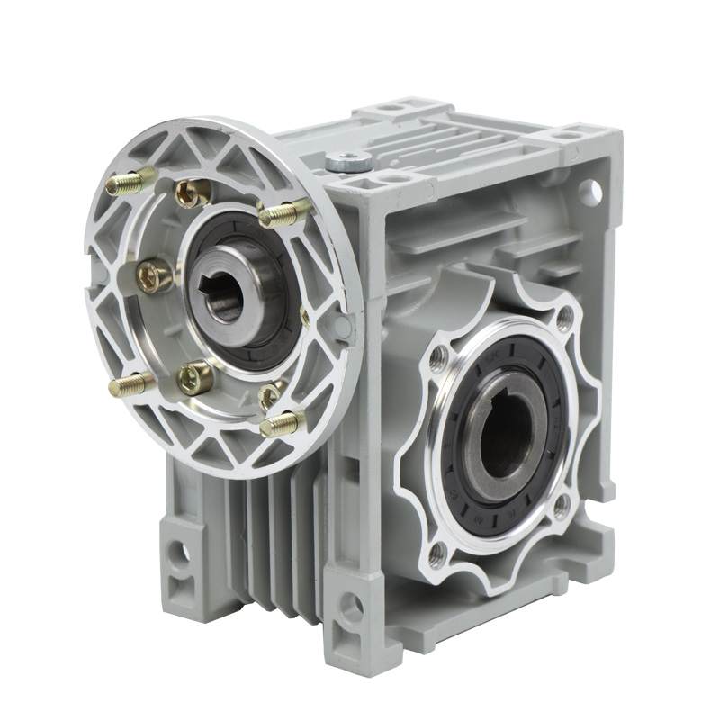
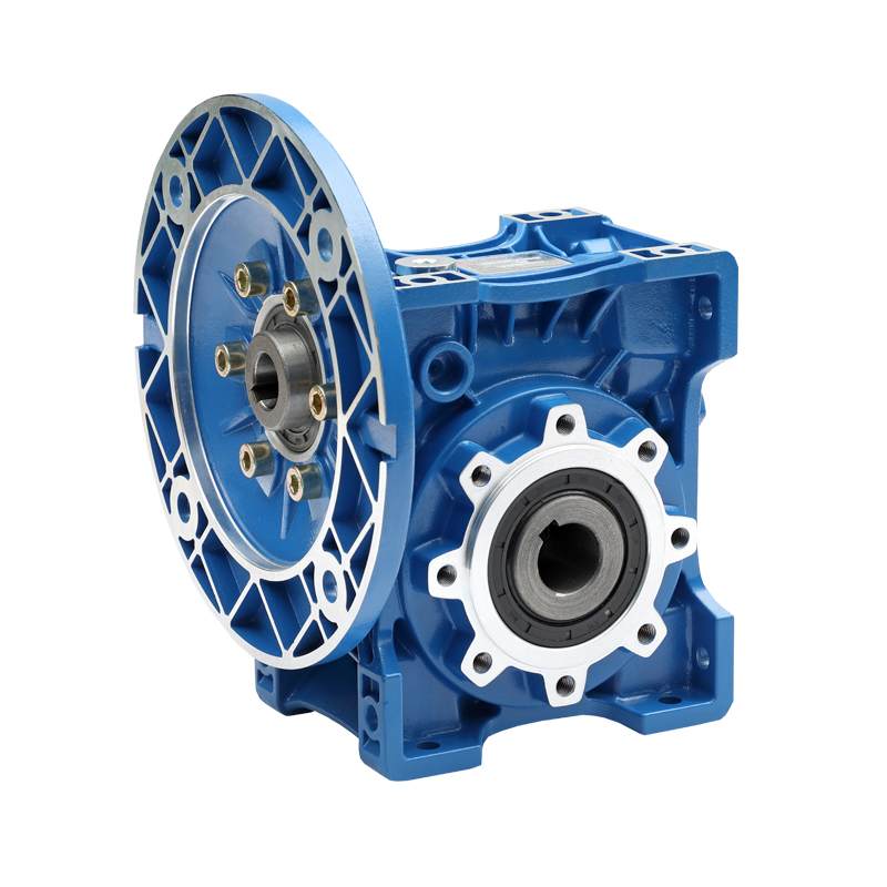
모터 플랜지란?? B5에 대한 완전한 엔지니어링 가이드, B14 & NEMA C-페이스 마운트
빠른 답변
모터 플랜지가 가공되어 있습니다., 펌프에 직접 동축으로 볼트로 고정할 수 있는 전기 모터의 구동 단부에 있는 디스크 모양의 장착면, 변속 장치, 또는 기타 구동 기계 — 별도의 베이스 또는 커플링 정렬 없음. 플랜지에는 정밀도가 있습니다 마개 (파일럿 또는 레지스터라고도 함) 모터의 중심을 잡는 것, 그리고 정의된 장착 구멍의 링 피치원 직경 (PCD). 국제표준 IEC 60034-7 다음과 같은 IM 코드로 플랜지 마운트를 정의합니다. B5 내 (대형 플랜지, 여유 공간/관통 구멍 = FF 유형) 그리고 IM B14 (작은 플랜지, 탭/나사 구멍 = FT 유형); 차원은 다음에서 비롯됩니다. IEC 60072. 북미에서는 동등한 개념이 다음과 같습니다. NEMA C-페이스 (나사산 구멍) 그리고 D-플랜지 (관통 구멍) 에 정의됨 MG 없음 1. 잘못된 플랜지 유형을 선택하는 것은 가장 일반적인 모터 주문 오류입니다..
모터 플랜지란?? (정의)
ㅏ 모터 플랜지 아파트다, 드라이브 끝 부분에 가공된 링 또는 플레이트 (의) 기존 장착 다리를 대체하거나 보완하는 모터. 베이스에 기대어 쉬는 것보다, 플랜지 장착형 모터가 고정되어 있습니다. 대면하다 구동 장비에. 플랜지와 스피곳은 베어링 하우징과 동일한 작업으로 가공되기 때문에, 모터 샤프트는 결합 보어와 자동으로 동심이 됩니다., 따라서 필드 정렬이 필요하지 않습니다..
모든 모터 플랜지는 세 가지 기능적 특징으로 구성됩니다., 이를 이해하는 것이 올바른 부분을 지정하는 열쇠입니다:
1. 마개 (조종사 / 등록하다 / 사개)
그만큼 마개 샤프트와 동심으로 가공된 짧은 원통형 숄더입니다.. 이는 기어박스 또는 펌프 하우징의 일치하는 홈에 삽입되어 실제 센터링 작업을 수행합니다. 볼트는 고정만 합니다.. IEC는 이를 스피곳 또는 파일럿이라고 부릅니다.; NEMA는 이를 사개 또는 등록 (치수 그리고). 샤프트에 대한 동심도는 아래에서 엄격하게 허용됩니다. IEC 60072-1.
2. 장착 구멍 및 피치 원 직경 (PCD)
볼트 구멍은 피치원 직경 (PCD), 볼트 원 직경이라고도 함 (BCD) 또는 NEMA AJ. 구멍은 다음 중 하나입니다. 정리 (~을 통해) 구멍 — 플랜지를 통해 탭 기계 하우징으로 볼트를 통과시킵니다. (IEC FF / 없다 D-플랜지) - 또는 두드림 (스레드) 구멍 — 기계 측면의 볼트를 모터면에 조입니다. (IEC FT / 없다 C-페이스).
3. 플랜지 외경 및 두께
이는 봉투와 로드 경로를 설정합니다.. 대형 FF/B5 플랜지의 외경은 다음과 같습니다. 모터 본체보다 크다; 작은 FT/B14 플랜지에서는 일반적으로 본체와 같거나 작습니다.. 플랜지는 모터의 전체 캔틸레버 중량과 토크 반응을 지탱해야 합니다., 그래서 그 두께는 구조적입니다, 화장품이 아닌, 치수.

플랜지 마운트 작동 방식: 단계별
- 스피곳이 하우징 구멍으로 들어갑니다.. 가공된 파일럿 직경은 가깝습니다. (종종 h7/H8) 기어박스의 결합 홈에 미끄러지듯 끼워맞춤, 펌프 어댑터, 또는 브래킷. 이는 모터를 반경 방향으로 배치하고 샤프트 축이 피동 샤프트 축과 일치하도록 강제합니다..
- 페이스 시트 플랫. 가공된 플랜지 면이 기계 면과 직각으로 접촉합니다., setting axial position and squareness (perpendicularity of the shaft to the mounting plane).
- The coupling engages. Because the shaft is now pre-aligned by the spigot, a rigid or short flexible coupling — or a direct splined/keyed input into a gearbox — can be joined without dial-indicator alignment.
- The bolts clamp. Bolts on the PCD are torqued to develop a clamp load that resists the motor’s weight and the reaction torque. Clamp force, not friction from a loose fit, keeps the joint rigid: F = T / (K·d), where T is bolt torque, d bolt diameter, and K the nut factor (~0.2 for dry steel).
- Load transfers through the flange. Weight and vibration flow from the motor, through the flange ring, into the machine structure — which is why flange concentricity and stiffness directly affect bearing life and vibration.
The result is a compact, self-aligning, floor-space-free drive. That is exactly why close-coupled pumps, speed reducers, and OEM machines overwhelmingly use flange motors instead of foot-mounted ones.
모터 플랜지 유형 비교 (IEC 60034-7)
IEC 60034-7 assigns each mounting arrangement an 나는 (International Mounting) code. The four flange-related codes below cover almost every industrial flange motor. The most important — and most confused — distinction is B5 vs. B14: B5 has clearance holes (bolt passes through the flange), while B14 has tapped holes (bolt threads into the flange).
| Code | IM number | Flange type | Hole type | Flange vs. body OD | 일반적인 사용 |
|---|---|---|---|---|---|
| B5 | 나는 3001 (B5 내) | Large flange (FF) | Clearance / ~을 통해 | Larger than body | 슬리퍼, 기어박스, 감속기, agitators |
| B14 | 나는 3601 (IM B14) | Small face flange (FT) | Tapped / 스레드 | Equal or smaller | Small pumps, 공작 기계, compact drives |
| B35 | 나는 2001 (IM B35) | 발 + 대형 플랜지 | Clearance (FF) + feet | Larger than body | Heavy reducers, 높은 토크, retrofits |
| B34 | 나는 2101 (IM B34) | 발 + face flange | Tapped (FT) + feet | Equal or smaller | Belt drive + face mount combo, OEM |
Vertical variants (shaft down = V1, shaft up = V3/V18) use the same flanges but need thrust-rated bearings and, outdoors, a rain canopy. For a foot-mounted comparison, see our guide to AC 대. DC 모터.

IEC 플랜지 대. 플랜지 없음 (글로벌 소싱)
North American equipment uses NEMA MG 1 terminology instead of IM codes. Functionally they map cleanly, but the dimensions and frame numbers differ, so an IEC B5 motor will ~ 아니다 bolt to a NEMA D-flange housing without an adapter.
| 특징 | IEC (60034-7 / 60072) | 없다 (MG 1) |
|---|---|---|
| Tapped-hole flange | FT flange = B14 | C-페이스 (예를 들어. 56씨, 143TC) |
| Through-hole flange | FF flange = B5 | D-플랜지 (예를 들어. 56디, 254TD) |
| Centering feature | Spigot / 조종사 / 등록하다 | Rabbet / 등록하다 (dim 그리고) |
| Bolt circle | Pitch circle diameter (PCD) | Bolt circle (dim AJ) |
| Flange OD | Flange outer diameter | 치수 BD |
| Size unit | Millimetres | Inches |
| Dimensional standard | IEC 60072-1 | MG 없음 1 / IEC 60072 |
FF 및 FT 플랜지 지정 설명
Under IEC 60072-1, a flange is named by its type letters plus the pitch circle diameter in millimetres. 그래서 FF265 means a through-hole (FF) flange with a 265 mm PCD; FT115 means a tapped (FT) flange with a 115 mm PCD. The table pairs common IEC frame sizes with their standard flange.
| IEC frame | Std. B5 flange (FF) | PCD (mm) | Spigot Ø N (mm) | Std. B14 flange (FT) |
|---|---|---|---|---|
| 63 | FF115 | 115 | 95 | FT75 |
| 71 | FF130 | 130 | 110 | FT85 |
| 80 | FF165 | 165 | 130 | FT100 |
| 90 | FF165 | 165 | 130 | FT115 |
| 100 / 112 | FF215 | 215 | 180 | FT130 |
| 132 | FF265 | 265 | 230 | FT165 |
| 160 | FF300 | 300 | 250 | FT215 |
| 180 | FF300 | 300 | 250 | - |
| 200 | FF350 | 350 | 300 | - |
Spigot diameter “N” is the pilot register the housing bore must match. Values follow IEC 60072-1; always confirm against the specific manufacturer datasheet before machining a mating part.
모터 플랜지 엔지니어링 데이터: 공차, 잔뜩 & 방식
A flange looks simple, but its performance is governed by tight geometric tolerances and a real mechanical load path. Getting these numbers right is what separates a vibration-free drive from premature bearing failure.
Concentricity and run-out tolerances (IEC 60072-1)
IEC 60072-1 defines two tolerance grades for the spigot and face: Normal (N) 그리고 Reduced (아르 자형) for precision applications. The spigot must be concentric to the shaft, and the mounting face perpendicular to it, within these limits (total indicator reading, TIR):
| Spigot Ø N (mm) | Concentricity — Normal (mm) | Concentricity — Reduced (mm) | Face perpendicularity — Normal (mm) |
|---|---|---|---|
| ≤ 250 | 0.10 | 0.05 | 0.10 |
| > 250 에게 500 | 0.125 | 0.063 | 0.125 |
| > 500 에게 800 | 0.16 | 0.08 | 0.16 |
Exceed these and the shaft runs eccentric to the driven bore, injecting a once-per-revolution radial force that shortens bearing L10 life and raises vibration.
Key formulas for flange-mounted drives
- Bolt clamp load: F = T / (K · d) — clamp force F from torque T, bolt diameter d, nut factor K (≈0.20 dry, ≈0.15 lubricated). Under-torqued flange bolts let the joint fret and loosen under vibration.
- Reaction torque on the flange: T = P × 9550 / N (N·m), with power P in kW and speed n in rpm. This is the torque the flange bolt pattern must react at start-up and stall.
- Bolt shear from reaction torque: 에프bolt = 2T / (N비 · PCD) — tangential load per bolt, with n비 bolts on the pitch circle diameter. Larger PCD = lower per-bolt load.
- Cantilever bending on the flange: M = W · Lcg — motor weight W acting at its center-of-gravity distance Lcg from the flange face; the reason large motors prefer B35 (foot + 플랜지) over B5 alone.
- Bearing L10 life: L10h = (10⁶ / 60N) · (C/P)³ for ball bearings — misalignment from a poor flange fit raises the equivalent load P and cuts life cubically (see SKF bearing calculator).
Worked example
ㅏ 7.5 kW, 1,450 rpm B5 motor on an FF265 flange (PCD 265 mm, 4 bolts): reaction torque 티 = 7.5 × 9550 / 1450 ≒ 49 N·m. Tangential load per bolt 에프bolt = 2 × 49 / (4 × 0.265) ≒ 92 N — small, so the bolts are sized by clamp/vibration, not shear. This confirms why correct preload torque matters more than bolt count on most flange motors.
Materials and typical thermal limits
Flanges are cast iron (heavy-duty rigidity), 알류미늄 (light OEM frames), or fabricated/stainless steel (washdown). Insulation class governs the surface heat the flange transmits into the driven machine: 클래스 B 130 ° C, F급 155 ° C, 클래스 h 180 ° C 당 IEC 60034-1 — relevant when a plastic pump adapter meets a hot motor flange.
플랜지 장착형 모터를 위한 최고의 애플리케이션
| 애플리케이션 | Preferred flange | 왜 |
|---|---|---|
| Close-coupled centrifugal pumps | B5 / D-플랜지 | Direct axial coupling, self-aligning, no baseplate |
| 기어박스 & speed reducers | B5 / B14 | Motor bolts straight to reducer input bell — see our 변속 장치 가이드 |
| Compact machine tools & 섬유 기계 | B14 / C-페이스 | Small footprint, tapped-hole face fits limited space |
| 믹서 & agitators (수직의) | B5 V1 | Shaft-down flange mount with thrust bearing |
| 컨베이어 & heavy reducers | B35 (foot + 플랜지) | Flange aligns, feet carry weight & 진동 |
| OEM pump/gear assemblies | B14 / C-페이스 | Standardised pilot for modular, interchangeable builds |
올바른 모터 플랜지를 선택하는 방법: 단계별
- Confirm the standard. IEC (metric, IM codes) 또는 NEMA (inch, C/D-face)? This is set by your existing machine, not preference.
- Read the mating housing. Measure the recess bore (this must equal the motor spigot Ø N / 그리고) and the bolt circle (PCD / AJ). These two numbers define the flange.
- Identify the hole type. Do bolts pass ~을 통해 the flange into a tapped housing (B5 / D-플랜지, FF) or thread into the motor face (B14 / C-페이스, FT)? This is the #1 mistake — verify with a photo or thread gauge.
- Match the frame & 샤프트. The flange PCD is tied to frame size; also confirm shaft diameter, 길이, and key so the coupling fits.
- Check load direction. Heavy motor, 진동, or overhung load? Step up to B35 (foot + 플랜지) rather than trusting the flange bolts alone.
- Specify tolerance grade. Precision spindles or high-speed pumps warrant the Reduced (아르 자형) concentricity grade, not Normal (N).
- Select material & enclosure. Cast iron for industrial rigidity, stainless for washdown, aluminium for light OEM; then pick IP/enclosure rating.
모터 플랜지의 일반적인 엔지니어링 실수
- Confusing B5 and B14. They look similar but B5 has clearance holes and B14 has tapped holes. A B14 ordered as B5 will not bolt on. This is the most frequent flange ordering error.
- Matching PCD but ignoring the spigot. Two flanges can share a bolt circle yet have different pilot diameters — the motor won’t center. Always match spigot Ø N (그리고) 그리고 PCD (AJ).
- Mixing IEC and NEMA. An IEC B5 flange will not fit a NEMA D-flange housing; the metric/inch dimensions differ. Use an adapter plate or order to the correct standard.
- Overloading a bare B5 flange. Using flange-only mounting for a heavy or overhung load overstresses the flange bolts and bends the mounting face. Move up to B35.
- Under-torquing the bolts. Insufficient clamp load lets the joint fret, loosen, and shift under vibration. Torque to spec using F = T/(K·d).
- Forcing a vertical mount. Turning a horizontal B5 motor shaft-down without a thrust-rated bearing (and rain canopy outdoors) leads to early bearing failure.
- Paint or burrs on the spigot/face. Contamination breaks the flat face contact and concentric fit, re-introducing the misalignment the flange was meant to remove.
모터 플랜지 문제 해결 표
| 문제 | 가능한 원인 | 해결책 |
|---|---|---|
| Motor won’t bolt to housing | Wrong flange type (B5 vs B14) or IEC/NEMA mismatch | Verify hole type & 기준; use adapter or correct motor |
| Bolts line up but motor won’t seat | Spigot Ø doesn’t match the housing recess | Match pilot register Ø N / 그리고, not just PCD |
| High vibration after mounting | Spigot concentricity out of tolerance, or burrs/paint on face | Clean & deburr faces; check TIR to IEC 60072-1 grade |
| Recurring bearing failure | Shaft misalignment from poor flange fit; 돌출된 하중 | Re-check spigot fit; add support or switch to B35 |
| Flange bolts keep loosening | Under-torque / no clamp preload; 진동 | Torque to spec, add thread-locker or lock washers |
| Flange face cracked or bent | Overhung/heavy load on flange-only (B5) mount | Upgrade to foot + 플랜지 (B35); check load path |
| Water in motor (vertical mount) | Shaft-up without seal / shaft-down without canopy | Add rain canopy or shaft seal; specify V-mount properly |
| Coupling still needs alignment | Non-precision (Normal) flange used on precision drive | Specify Reduced (아르 자형) tolerance grade flange |
자주 묻는 질문
What is a motor flange used for?
A motor flange lets a motor bolt directly and coaxially onto a pump, 변속 장치, or machine without a separate base or dial-indicator alignment. The machined spigot centers the shaft automatically, saving floor space and installation time.
What is the difference between a B5 and B14 flange?
A B5 flange is large, has clearance (~을 통해) 구멍, and its outer diameter is bigger than the motor body — the bolt passes through the flange into the machine. A B14 flange is smaller, has tapped (스레드) holes on the face, and the bolt threads into the motor. Confusing the two is the most common ordering error.
What is the spigot (등록하다) on a motor flange?
The spigot — also called the pilot, 등록하다, or NEMA rabbet — is a precision machined shoulder concentric to the shaft. It fits into a matching bore in the driven equipment and does the actual centering; the bolts only clamp. Its diameter must match the housing exactly.
Are IEC and NEMA flanges interchangeable?
아니요. IEC flanges (B5/B14, metric, IM codes) and NEMA flanges (D-flange/C-face, inch) use different dimensions and frame numbering. An IEC motor will not bolt to a NEMA housing without an adapter plate, even if the concepts are equivalent.
What does FF265 or FT115 mean?
Under IEC 60072-1 the number is the pitch circle diameter in millimetres. FF265 is a through-hole flange with a 265 mm PCD; FT115 is a tapped-hole flange with a 115 mm PCD. The letters give the hole type (FF = clearance, FT = tapped).
When should I use B35 instead of B5?
Use B35 (foot + 플랜지) when the motor is heavy, carries an overhung load, or is subject to strong vibration. The feet carry the weight and damp vibration while the flange still aligns the drive — reducing stress on the flange bolts and face.
플랜지 장착 모터에 Greensky를 선택하는 이유?
부터 2011, 그린스카이 파워 has engineered BLDC 모터, 브러시드 DC 모터, 스테퍼 모터, 그리고 기어박스 with correctly machined flanges for OEM customers in over 50 국가. When the mounting interface has to be right the first time, our engineers spec the flange with you — spigot, PCD, tolerance grade, and standard.
- Both standards: IEC B5/B14/B35 and NEMA C-face / D-플랜지, plus custom pilot diameters.
- Precision machining: spigot concentricity and face perpendicularity held to IEC 60072-1 grades.
- Integrated drives: 모터 + gearbox supplied as a matched flange assembly — no adapter guesswork.
- 100% 테스트: every unit run-tested; run-out and vibration verified.
- 표준 준수: designed to IEC 60034 / MG 없음 1 practice; ISO, CE certified.
- OEM/ODM support: full engineering help through United Motion Inc. 북미에서 & 유럽.
참조
- IEC 60034-7, Rotating electrical machines — Classification of types of construction, mounting arrangements and terminal box position (IM code). https://webstore.iec.ch/publication/2765
- IEC 60072-1, Dimensions and output series for rotating electrical machines — Frame numbers 56 에게 400 and flange numbers 55 에게 1080. https://webstore.iec.ch/publication/351
- IEC 60034-1, 회전 전기 기계 - 정격 및 성능. https://webstore.iec.ch/publication/60034-1
- MG 없음 1, 모터 및 발전기 (C-페이스, D-플랜지, AJ/AK dimensions). https://www.nema.org/standards/view/motors-and-generators
- MG 없음 1-2009 (full text, law.resource.org). https://law.resource.org/pub/us/cfr/ibr/005/nema.mg-1.2009.pdf
- 씨줄, Low voltage motors — Mounting arrangements and IM codes (technical guide). https://new.abb.com/motors-generators/iec-low-voltage-motors
- 지멘스, SIMOTICS General Purpose Motors — Types of construction / mounting. https://www.siemens.com/global/en/products/drives/electric-motors.html
- SKF, 베어링 정격 수명 (L10) and mounting/alignment guidance. https://www.skf.com/group/support/engineering-tools/bearing-calculator
- IEEE Standard 112, Test Procedure for Polyphase Induction Motors and Generators. https://standards.ieee.org/ieee/112/4703/
- 우리를. 에너지학과, Motor Systems — Energy Conservation Program (10 CFR 부분 431). https://www.energy.gov/eere/motors