
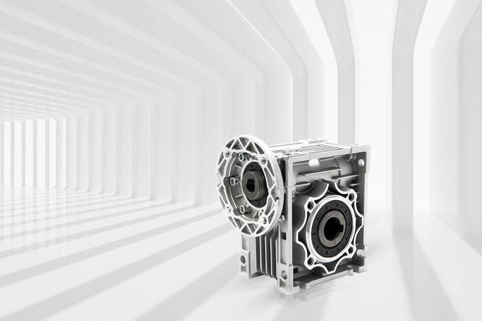
Everything to Know About Worm Gears: Espèces, Efficacité, Self-Locking & Sélection
Réponse rapide
A worm gear (worm drive) is a right-angle gear set that transmits motion between two non-parallel, non-intersecting shafts — usually at 90° — through a helical screw (the worm) that meshes with a toothed wheel (the worm wheel). Its defining traits are a very high single-stage reduction ratio (5:1 pour 100:1 in one stage), lisse, fonctionnement silencieux, and the ability to self-lock so the output cannot back-drive the input when the lead angle is small enough.
Efficiency is lower than other gear types because the mesh is dominated by sliding contact: single-start (autobloquant) units run 40–50%, while multi-start units reach 78–92%. This guide covers how worm gears work, the AGMA 6034 / ISO 14521 normes, the efficiency and self-locking formulas, material pairings (hardened-steel worm + bronze wheel), step-by-step selection, and troubleshooting.
What Is a Worm Gear? (Définition)
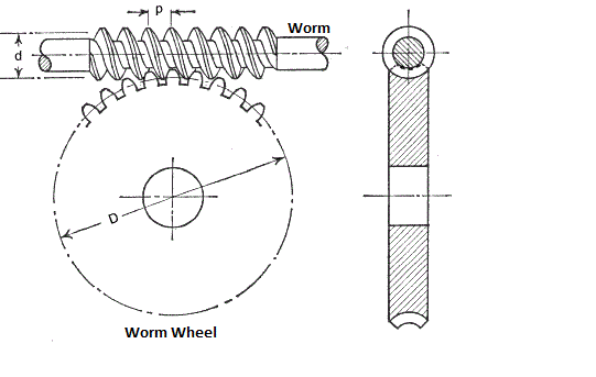
UN vis sans fin — also called a worm drive ou boîte de vitesses à vis sans fin when housed as a reducer — is a gear system that transmits motion and power between two non-parallel, non-intersecting arbres, almost always at a 90° right angle. It has two components:
- Le ver — a shaft with a continuous helical thread, essentially a screw. It is the input member and usually the driving element.
- The worm wheel (vis sans fin) — a toothed wheel whose curved teeth are conjugate to the worm’s helical profile. It is the output member. (Note: some sources use “vis sans fin” for the wheel alone; in this article vis sans fin means the complete assembly.)
Because the shafts are perpendicular and offset, a worm gear set always changes the direction of rotation by 90° — a geometric property no other en une seule étape reducer provides in such a compact envelope. The idea is ancient: Archimedes described the screw mechanism around 250 BC, et le “Archimedean worm” is still a basic form today.
Three numbers define any worm gearbox at the most fundamental level: le ratio de réduction (how much the output slows), le couple de sortie (continuous force the output can deliver), et le center distance (distance between the two shaft axes, which sets the physical size). Everything else on a spec sheet — thermal rating, facteur de service, contrecoup, mounting — flows from these.
Why Engineers Choose Worm Gears
- High single-stage ratio: 5:1 pour 100:1 in one stage, where spur/helical gears need two or three stages to reach the same ratio.
- Self-locking option: at high ratios the output mechanically locks when the motor stops — no brake needed.
- Calme, mouvement fluide: teeth engage gradually over a large contact area; typical 55–62 dB vs 62–75 dB for helical units.
- Compact right-angle package: small footprint for the torque delivered.
- Shock-load tolerance: the conforming (line/area) contact spreads load well.
The trade-off is efficiency and heat. The mesh is mostly sliding contact, so a large share of transmitted power becomes heat — the single most misunderstood and misspecified parameter in worm-gear selection.
How a Worm Gear Works: Étape par étape
The worm-drive action is best understood as a screw turning a wheel — but the physics is helical-gear meshing, not pure threading.
- The worm rotates as the input. Its helical thread is the driving surface. Rotating it one full turn advances the worm wheel by exactly the number of thread starts.
- The thread pushes the wheel teeth. As the worm turns, its flank contacts a wheel tooth, slides along it, engages fully, and releases — a continuous, progressive meshing. The helix direction and pressure angle of the worm must match the wheel, and the worm’s axial pitch must equal the wheel’s circular pitch, or the set will not mesh.
- Speed is reduced by the tooth count. A single-start worm advances the wheel one tooth per revolution; a 40-tooth wheel therefore gives 40:1. Two starts give 20:1 from the same wheel. The ratio is set purely by geometry: i = Z2 / Z1 (wheel teeth ÷ worm starts).
- Torque is multiplied. By conservation of power (ignoring losses), the slower output carries proportionally more torque: Tout =Tdans × je × n. This is why a small worm can hold a heavy load.
- Sliding dominates the contact. Unlike spur/helical gears that roll, the worm thread slides across the wheel face. That sliding is what creates high friction, efficacité inférieure, chaleur, and — at a shallow lead angle — self-locking.
- Self-locking appears when the angle is shallow enough. If the worm’s lead angle (γ) is smaller than the mesh friction angle (ρ′), the wheel cannot push the worm backward; the output locks when the motor de-energizes.
Single vs. Multi-Start Worms
The number of starts (thread heads, Z1) is the primary lever for both ratio and efficiency:
- Single-start (Z1 = 1): shallow lead angle, rapport élevé, strong self-locking, but low efficiency (40–50%).
- Double-start (Z1 = 2): moderate lead angle, less self-locking, efficiency 50–78%.
- Multi-start (Z1 = 3–4): steep lead angle, haute efficacité (78–92%) but generally not self-locking.
Worm Gear Types Compared
Worm sets are classified by how the worm and wheel “wrap” around each other. The enveloping form dictates contact area, load capacity, et le coût.
| Taper | Geometry | Contact | Capacité de charge | Utilisation typique |
|---|---|---|---|---|
| Non-enveloping (non-throated) | Cylindrical worm, plain wheel | Point / small area | Faible | Small instruments, light duty |
| Single-enveloping (single-throated) | Cylindrical worm, concave wheel | Line contact | Moyen-élevé | Machine tools, convoyeurs, actionneurs |
| Double-enveloping (double-throated / hourglass) | Hourglass worm + concave wheel | Largest area | Highest | Metallurgy, heavy presses, precision heavy load |
Enveloping vs. planar double-enveloping: a standard enveloping worm has a cylindrical worm with a throated wheel. UN double-enveloping (par ex., Cone Drive’s Envex®) throats both members so the teeth maintain uniform contact through the mesh — highest load capacity but the most demanding to machine. For most industrial NMRV-class reducers, single-enveloping is the cost/performance sweet spot.
Vis sans fin vs. Other Gear Types
Choosing worm over spur, hélicoïdal, bevel, or planetary depends on ratio, efficacité, autobloquant, and envelope.
| Criterion | Worm gear | Éperon | Hélicoïdal | Planétaire |
|---|---|---|---|---|
| Rapport à un étage | 5:1 – 100:1 | ≤ 6:1 | ≤ 10:1 | 3:1 – 10:1 |
| Efficacité (typique) | 40–92% (ratio-dependent) | 96–99% | 95–98% | 90–97% |
| Autobloquant | Oui (rapport élevé) | Non | Non | Non |
| Shaft arrangement | Right-angle, non-intersecting | Parallel | Parallel | Coaxial |
| Bruit | Très faible (55–62 dB) | Plus haut | Low–medium | Low–medium |
| Génération de chaleur | Haut (sliding) | Faible | Faible | Low–medium |
| Cost at high ratio | Low–medium | Haut (needs stages) | Haut (needs stages) | Moyen-élevé |
Règle générale: pick a worm drive when you need a large right-angle reduction, quiet running, or self-locking in one stage. Pick spur/helical/planetary when efficiency and continuous-duty thermal load dominate (par ex., high-speed conveyors, traction). See also our gearbox vs. motoréducteur guide.
Worm Gear Efficiency by Ratio
Efficiency falls monotonically with ratio because a higher ratio forces a shallower lead angle. The table consolidates AGMA / ISO 14521 methodology with manufacturer acceptance-test data (run-in unit, ~40°C oil, PAO synthetic — the most favorable normal condition). Cold-start runs 5–10% lower.
| Rapport (je) | Lead angle γ (approx.) | Efficiency η (mineral) | Efficiency η (PAO synth.) | Autobloquant? |
|---|---|---|---|---|
| 5:1 | 21°–26° | 86–90% | 89–93% | Non |
| 10:1 | 14°–18° | 80–85% | 84–88% | Non |
| 20:1 | 8°–11° | 72–78% | 76–82% | Borderline |
| 30:1 | 6°–8° | 68–74% | 73–79% | Typically yes |
| 50:1 | 4°–6° | 64–70% | 69–75% | Oui |
| 80:1 | 2.8°–4° | 58–64% | 63–69% | Oui |
| 100:1 | 2.3°–3.5° | 55–61% | 60–67% | Oui |
Material Pairing: Hardened-Steel Worm + Bronze Wheel
The worm and wheel are deliberately different hardnesses. A hard steel worm against a softer bronze wheel prevents adhesive wear (galling): the bronze sacrifices itself slowly while protecting the more expensive worm. This is why bronze-wheel replacement is the most common major service item (typically 6–10 years of continuous duty).
| Member | Common material | Hardness / spec | Role |
|---|---|---|---|
| Ver | Case-hardened steel (20CrMnTi, 17CrNiMo6, 16MnCr5) | HRC 58–62 | Hard driver, wear-resistant |
| Worm wheel — general | Phosphor bronze (CuSn12Ni2) | HB 95–115 | Low-friction bearing surface |
| Worm wheel — heavy duty | Aluminum bronze (CuAl10Ni) | High strength | Higher load, wear resistance |
| Worm wheel — light duty | Cast iron | — | Cost-sensitive, low load |
| Logement | ADC12 aluminum die-cast (std) / EN-GJL-250 cast iron (lourd) | — | Contains pair + lubricant |
| Lubricant | ISO VG220 PAO (std) / VG320 (reversing) / PAG (high-temp) | — | EHL film, governs η & life |
Worm Gear Engineering Data: Formules & Limits
These are the equations an engineer actually uses when specifying a worm drive. All conform to AGMA 6034-B92 (ANSI/AGMA 6034) et ISO 14521 methodology.
1. Ratio de réduction
i = Z2 / Z1 — wheel teeth (Z2) ÷ worm starts (Z1). Keep Z2 > 28 to avoid undercutting.
2. Lead angle
γ = arctan( Z1 · m / d1 ) = arctan( Z1 / q ) — where m is the axial module, d1 the worm pitch diameter, and q = d1/m the diameter factor. The lead angle is the single most important efficiency variable.
3. Efficacité (worm driving)
η = tan γ / tan( γ + ρ′ ), where the virtual friction angle ρ′ = arctan( μ / cos αn ), μ is the mesh friction coefficient (set by sliding velocity, lubricant, material, température), and αn is the normal pressure angle (typically 20°, so cos αn ≈ 0.940).
The practical back-drive form is also useful:
ηback = tan( γ − ρ′ ) / tan γ
4. Self-locking condition
Self-locking when γ < ρ′ (equivalently, when λ < φ, the equivalent friction angle). Below roughly 5° lead angle, most sets self-lock. Remember the trade: the same shallow angle that gives self-locking also gives the lowest efficiency (often < 50%).
5. Couple de sortie
Tout = Tin × i × η — always include η; à 50:1/55% you lose 45% of input torque to friction.
6. Center distance
a = m ( q + Z2 + 2x ) / 2 — where x is the addendum-modification coefficient. Center distance sets the unit size and is fixed by the housing; getting it wrong causes misalignment wear.
7. Thermal limit (the rating that actually bites)
The AGMA power rating is based on 10 h of continuous uniform load and is governed by pitting/wear resistance et by heat dissipation. Keep oil temperature ≤ 80–90°C; above this, lubricant viscosity collapses and the mesh risks scuffing failure. The allowable thermal power is Pth = ks · A · ( Toil − Tambient ).
Worked example — why efficiency is a thermal problem, not a footnote
Considérez un 3 kW conveyor drive at 50:1, continu 18 h/day. À 75% efficacité, lost power = 3 × 0.25 = 0.75 kW of heat, continuously. À 55% efficacité (single-start, autobloquant), lost power = 3 × 0.45 = 1.35 kW. Le 0.6 kW difference behaves like a 600 W space heater sealed inside the housing — raising oil temperature 15–20°C, dropping viscosity ~40%, and triggering a self-reinforcing scuffing failure months later. The fix is a multi-start worm (higher γ, higher η) or forced/larger cooling — not a bigger motor.
Best Applications for Worm Gears
Worm drives earn their place wherever a large right-angle reduction, quiet running, or self-locking matters more than peak efficiency.
| Application | Why worm gear fits | Typical ratio |
|---|---|---|
| Ascenseurs & lifting hoists | Self-locking holds the load when power fails | 30:1 – 80:1 |
| Grues, treuils, anchor windlasses | Couple élevé, self-locking safety | 20:1 – 60:1 |
| Systèmes de convoyeurs | Compact, rapport élevé, calme | 10:1 – 40:1 |
| Automotive power steering | Right-angle, lisse, reversible feel | 15:1 – 25:1 |
| Valve actuators & dampers | Self-locking holds position without a brake | 40:1 – 100:1 |
| Solar tracking systems | Holds panel angle against wind, low power | 30:1 – 60:1 |
| Robotique & precision positioning | Backlash control, right-angle joints | 20:1 – 100:1 |
| Conditionnement & machines alimentaires | Calme, washdown housings available | 10:1 – 30:1 |
| Stage & theater rigging | Autobloquant, silencieux, safe | 30:1 – 80:1 |
For battery- or efficiency-critical motion where a worm’s losses are unacceptable, notre Moteurs BLDC paired with réducteurs planétaires are the usual alternative.
How to Select a Worm Gear: Étape par étape
- Define the ratio. From required output speed: je = ndans / nout. Worm sets cover 5:1–100:1 in one stage.
- Define the output torque. Load torque × service factor. Then back-calculate the needed input torque: Tdans =Tout / ( je × n ).
- Pick the start count (Z1). Need self-locking? Use single-start. Need efficiency for continuous duty? Use double/multi-start. This is the key efficiency lever.
- Size the center distance. Choose the smallest standard center distance whose AGMA-rated thermal and pitting capacity exceeds your continuous power at the operating ratio. Ne pas size on peak torque alone.
- Select the material pair. Hardened-steel worm + phosphor-bronze wheel for general duty; aluminum bronze for heavy/reversing; cast iron only for light duty.
- Specify lubrication & refroidissement. ISO VG220 PAO synthetic as standard; VG320 for high-cycle reversing; PAG for high temperature. For continuous high-load, confirm the housing can shed the lost heat (Pth).
- Confirm self-locking (if required). Verify γ < ρ′ at your operating temperature — note that hot lubricant lowers μ and can break self-locking on borderline designs.
- Verify mounting & alignment. Match the motor flange (IEC B5/B14 or NEMA C-face), then ensure coaxiality, perpendicularity, and the correct center distance at installation to avoid eccentric wear.
Common Worm Gear Engineering Mistakes
- Sizing on peak torque, ignoring thermal rating. The AGMA rating is a 10-hour continuous-duty limit governed by heat. A unit fine for a 2-minute peak will cook under 18-hour continuous load. Always check Pth.
- Assuming high efficiency. À 50:1 a self-locking worm is ~55% efficient; you lose ~45% of input torque and ~1.3 kW of 3 kW as heat. Budget motor power and cooling accordingly.
- Assuming it can be back-driven. Self-locking sets (single-start, rapport élevé) cannot be reversed by the load. Using one where the application needs back-driving motion is a design error — and relying on self-locking as the sole safety brake can fail if the oil warms up.
- Using the wrong lubricant. Worm meshes need EP worm-grade oil (ISO VG220/320), not ordinary engine or gear oil. The wrong oil raises μ, drops efficiency, and causes scuffing.
- Wrong alignment / center distance. Off-center or non-perpendicular mounting creates eccentric load and poor mesh, accelerating wear and noise.
- Choosing the wrong start count. Specifying a single-start when efficiency matters (continuous conveyor) or a multi-start when self-locking is safety-critical. Decide Z1 from the efficiency/self-lock trade first.
Worm Gear Troubleshooting: Problème → Cause → Solution
| Problème | Cause probable | Solution |
|---|---|---|
| Housing overheats | Low oil level, wrong lubricant, surcharge, mauvaise dissipation de la chaleur | Top up to correct level, use ISO VG220/320 EP worm oil, reduce load or add forced cooling |
| Bruit excessif / vibration | Misalignment, worn wheel, failed bearings | Re-check coaxiality & perpendicularity, replace worm wheel, remplacer les roulements |
| Self-locking fails (load back-drives) | Multi-start worm (large γ), warm oil lowered μ, advanced wear | Use single-start worm, keep oil cool, add a holding brake for safety-critical lifts |
| Oil leaks | Worn shaft seal (FKM), blocked breather | Replace double-lip Viton seal, clear the breather vent |
| Scuffing / tooth scoring | Oil too hot, boundary lubrication lost, contamination | Improve cooling & lubrification, filter oil, reduce duty |
| Premature wheel wear | Wrong center distance, incorrect material pair, abrasives in oil | Re-establish correct center distance, use hardened-steel worm + bronze wheel, filter |
| Output torque below spec | Efficiency over-estimated, unit undersized | Recompute with actual η (y compris. rapport), select larger center distance |
| Input shaft seizes | Foreign object, bearing lock-up, severe overload | Strip & inspect, remplacer les roulements, verify load vs. AGMA rating |
Foire aux questions
What is the difference between a worm gear and a worm wheel?
Le ver is the screw-shaped input shaft; le worm wheel (ou engrenage à vis sans fin) is the toothed output wheel that meshes with it. Together they form the worm gear conduire. Some texts use “vis sans fin” for the whole assembly and others for the wheel alone — clarify which when reading a spec sheet.
Are worm gears self-locking?
They can be. Self-locking occurs when the lead angle γ is smaller than the mesh friction angle ρ′ (γ < ρ′), which happens at high ratios with single-start worms (roughly 30:1 and above). Multi-start worms are generally not self-locking. Note that hot oil lowers μ and can defeat borderline self-locking, so never rely on it as the sole safety brake in a lift.
What is a good efficiency for a worm gear?
It depends entirely on ratio and start count. Single-start self-locking units run 40–50%; double-start 50–78%; multi-start 78–92%. At a fixed ratio, expect efficiency to fall as the ratio rises — a 100:1 worm box is inherently ~55–67%, tandis qu'un 5:1 can reach 89–93%.
When should I pas use a worm gear?
Avoid worm drives for high-speed, continuous-duty, efficiency-critical applications (par ex., high-throughput conveyors, traction) where the sliding losses become a thermal and energy penalty. Planetary or helical reducers are better there. Also avoid them where the load must back-drive the input.
What lubrication do worm gears need?
A dedicated extreme-pressure worm-gear oil — typically ISO VG220 synthetic (PAO) as standard, VG320 for high-cycle reversing, PAG for high temperature. Ordinary engine or spur-gear oil is the wrong choice and causes scuffing. Change oil after the first ~400 hours and then about every 4,000 heures.
How long do worm gearboxes last?
With correct lubrication and load, the bronze wheel typically lasts 6–10 years of continuous service before replacement; the hardened-steel worm usually outlasts several wheels. Bearing and seal life, plus oil cleanliness, dominate the practical service interval.
Why Choose Greensky for Worm Gear Motors & Custom Drives?
When a standard catalog worm reducer fits, the big brands are fine. Quand vous avez besoin d'un moteur + worm-gear reducer as one engineered assembly, a custom center distance or ratio, or flexible volumes, Puissance Greensky is the OEM/ODM partner. Depuis 2011 we have built worm-gear reducers (nmrv / WP series), BLDC, CC brossé, et moteurs pas à pas with matched gearheads for customers in 50+ des pays.
- Integrated drivetrains: moteur + worm reducer supplied as one concentric assembly — no adapter guesswork, correct flange every time (IEC B5/B14 or NEMA C-face).
- Custom ratios & center distances: tailored reduction, self-locking or high-efficiency (multi-start) builds to your load profile.
- Thermal-aware sizing: we size to the AGMA continuous-duty thermal limit, not just peak torque, so your unit does not cook in continuous operation.
- Flexible MOQ & lead time: from prototype to mass production.
- Standards practice: conçu selon CEI 60034 / PAS DE MG 1 motor practice; ISO and CE certified.
- Assistance locale: engineering help through our North America & Europe channels.
Références
- AGMA 6034-B92 (ANSI/AGMA 6034), Practice for Enclosed Worm Gear Speed Reducers and Gearmotors. https://www.agma.org/standards/
- ISO 14521, Worm-gear pairs — Calculation of load capacity. https://www.iso.org/standard/54551.html
- CEI 60034-1, Machines électriques tournantes — Caractéristiques nominales et performances. https://boutique en ligne.iec.ch/publication/60034-1
- PAS DE MG 1, Moteurs et générateurs. https://www.nema.org/standards/view/motors-and-generators
- ISO 6336, Calculation of load capacity of spur and helical gears (strength context). https://www.iso.org/standard/76425.html
- SKF, Durée de vie nominale des roulements (L10), montage & lubrication guidance. https://www.skf.com/group/support/engineering-tools/bearing-calculator
- Siemens / Flender, Gear unit engineering — worm gear drive technology. https://www.siemens.com/global/en/products/automation/drive-technology/gear-units.html
- Norme IEEE 112, Procédure de test pour les moteurs et générateurs à induction polyphasés. https://standards.ieee.org/ieee/112/4703/
- NOUS. Ministère de l'Énergie, Moteur & Drive Systems — Energy Efficiency. https://www.energy.gov/eere/motors
- Cone Drive (a Regal Rexnord brand), Double-enveloping (Envex®) worm gear technology. https://www.conedrive.com/technology/