
What’s the Difference Between a Gearbox and a Gear Motor?
Hurtigt svar
EN gearkasse is a standalone mechanical transmission device that reduces speed and multiplies torque from an external motor, while a gearmotor integrates an electric motor and gearbox into a single factory-matched unit. The core difference is integration: a gearbox requires separate motor selection, shaft alignment, and coupling installation, whereas a gear motor arrives pre-assembled, testet, and optimized for compact, reliable operation. According to the IEA Electric Motor Systems Platform, motor-driven systems account for 53% of global electricity consumption, making the choice between these two configurations critical for energy efficiency, maintenance cost, and total cost of ownership.
What Is a Gearbox?
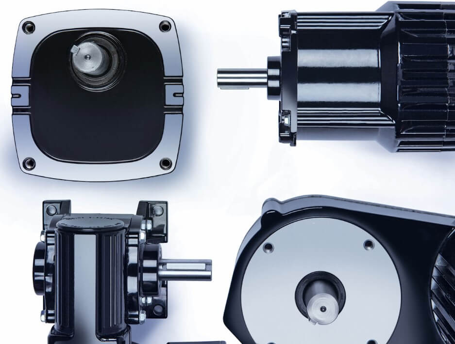
A gearbox—also called a gear reduktion eller speed reducer—is a mechanical device consisting of gear sets housed within an enclosure. It does ikke generate power; instead, it modifies the speed, drejningsmoment, and direction of rotational motion transmitted from an external power source (elektrisk motor, motor, or turbine) to a driven load. Det IEC 60034-1 standard classifies gearboxes as mechanical transmission components, while INGEN MG 1 provides dimensional and performance guidelines for motors paired with gearboxes in the North American market.
Core Functions of a Gearbox
- Speed reduction: Lowers the input rotational speed to match load requirements
- Torque multiplication: Increases output torque proportional to the gear ratio and efficiency
- Direction change: Redirects rotational axis (F.eks., bevel gears for 90° turns)
- Load matching: Matches motor output characteristics to the driven equipment’s demand curve
- Inertia matching: Reduces reflected load inertia to improve motor control stability
Gearbox Types by Transmission Architecture
| Type | Gear Configuration | Typisk effektivitet | Max forhold (Single Stage) | Bedst til |
|---|---|---|---|---|
| Spur Gearbox | Parallel shafts, straight teeth | 95–98 % | ~10:1 | Low-speed, low-noise applications |
| Helical gearkasse | Parallel shafts, angled teeth | 96–98 % | ~15:1 | High-load, quiet industrial drives |
| Konisk gearkasse | Intersecting shafts (90°) | 94–97% | ~6:1 | Direction change, transportørsystemer |
| Snekkegearkasse | Worm wheel + skrue | 60–90 % | ~60:1 | High reduction, self-locking needs |
| Planetarisk gearkasse | Sol + planet + ring gears | 95–97% | ~10:1 | Høj momenttæthed, robotteknologi |
Efficiency data sourced from Siemens SIMOGEAR technical specifications and IEEE research on planetary gear optimization (DOI: 10.1109/TMECH.2019.2946403).
What Is a Gear Motor?
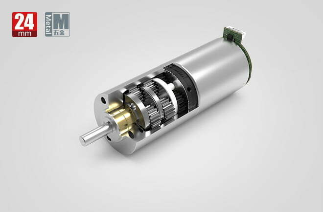
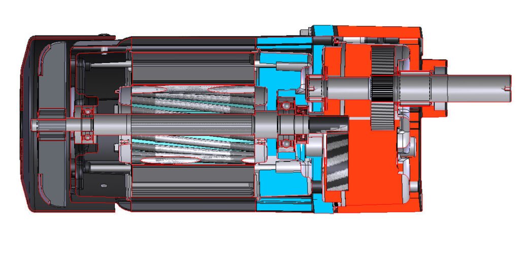
A gear motor (eller gearmotor) is an integrated drive unit that combines an electric motor and a gearbox into a single, factory-matched assembly. The motor’s rotor shaft typically serves as the input pinion for the first gear stage, eliminating the need for external couplings, alignment procedures, and separate mounting hardware. Gear motors are classified under IEC 60034-1 as complete motor systems and must comply with efficiency requirements defined in IEC 60034-30-1 og den DOE 10 CFR del 431 regulation.
Types of Gear Motors
| Motortype | Gearbox Options | Typical Power Range | Efficiency Class | Common Applications |
|---|---|---|---|---|
| AC induktionsgearmotor | Helical, bevel, orm | 0.09–55 kW | IE2–IE4 | Transportører, mixere, pumper |
| Brushed DC Gear Motor | Spur, planetary | 1–1500 W | 70–85 % | Automotive seats, vinduesviskere |
| BLDC gearmotor | Planetarisk, spiralformet | 20–750 W | 85–92 % | Robotik, Agvs, medicinsk |
| Servo Gear Motor | Planetarisk, bevel | 0.1–30 kW | IE4–IE5 | CNC, emballage, præcision |
Benefits of Integrated Gear Motors
- Factory-matched optimization: Motor and gearbox are engineered together, ensuring the pinion, Gearforhold, and thermal characteristics are perfectly aligned—eliminating the guesswork of separate sizing.
- Compact footprint: By using the motor shaft as the input pinion, the overall length is significantly reduced compared to a separate motor + gearkasse + coupling configuration.
- Reduced alignment failures: No external coupling means no misalignment-induced bearing failures, which account for approximately 30% of premature gearbox failures per SKF bearing life analysis.
- Simplified maintenance: Fewer mechanical interfaces mean fewer wear points and simplified lubrication management.
- Higher system efficiency: Eliminating coupling losses (typically 1–3% per coupling) and optimizing the motor-gear interface improves overall system efficiency by 2–5%.

How a Gearbox Works — Step-by-Step
- Power input: An external motor delivers rotational energy to the gearbox input shaft via a coupling or direct connection.
- First gear mesh: The input shaft drives the first gear stage (tandhjul), which meshes with a larger gear to achieve initial speed reduction and torque increase.
- Subsequent stages: For multi-stage gearboxes, the output of each stage becomes the input of the next, progressively reducing speed and multiplying torque.
- Bearing support: Bearings at each shaft position maintain gear alignment and support radial/axial loads. Per SKF bearing rating life, L10 life is calculated as L10 = (C/P)^p, where C is the dynamic load rating, P is the equivalent load, and p = 3 for ball bearings or 10/3 for roller bearings.
- Smøring: Oil bath or grease lubrication reduces friction between meshing gears and dissipates heat. Det IEC 60034-1 standard specifies operating temperature limits based on insulation class.
- Power output: The final stage delivers reduced speed and multiplied torque to the driven load via the output shaft.
How a Gear Motor Works — Step-by-Step
- Electrical input: Power is supplied to the motor winding (AC, DC, or BLDC), generating a magnetic field that interacts with the rotor.
- Rotor rotation: The electromagnetic field produces torque on the rotor, which rotates at a speed determined by supply frequency (AC) or voltage (DC).
- Integrated pinion drive: The rotor shaft extends directly into the gearbox housing, where the machined pinion gear engages the first reduction stage—no coupling required.
- Multi-stage reduction: Gear stages progressively reduce speed and multiply torque. For eksempel, -en maxon GPX 32 planetary gearhead achieves a 138:1 ratio across 3 stages with 75% efficiency and 5 N·m continuous torque.
- Termisk styring: The motor and gearbox share a common housing, allowing heat from both components to dissipate through the same structure. Per IEC 60034-1, Class F insulation permits winding temperatures up to 155°C.
- Output delivery: The output shaft delivers the final torque and speed to the application, with the entire unit pre-tested and certified as a single assembly.
Gearbox vs. Gearmotor: Feature Comparison Table
| Feature | Gearkasse (Standalone) | Gearmotor (Integreret) |
|---|---|---|
| Strømkilde | External motor required | Motor included in unit |
| Integration Level | Mechanical component only | Motor + gearbox combined |
| Installation Complexity | High—requires shaft alignment, kobling, mounting | Low—plug-and-play, pre-assembled |
| Footprint | Larger overall assembly | Kompakt, space-saving |
| Motor Selection Flexibility | High—any compatible motor can be paired | Limited to factory-installed motor |
| Coupling Losses | 1–3% per coupling interface | None—direct pinion integration |
| System Efficiency | Sænke (misalignment + coupling losses) | Højere (2–5% improvement typical) |
| Misalignment Risk | High—common failure mode | Minimal—factory-aligned |
| Opretholdelse | Motor and gearbox serviced separately | Fewer interfaces, simplified schedule |
| Failure Replacement | Individual component replacement | Entire unit may need replacement |
| Initial Cost | Sænke (gearkasse + separate motor) | Højere (integrated unit) |
| Long-term TCO | Højere (installation + vedligeholdelse + downtime) | Often lower (reduced labor + downtime) |
| Best Power Range | >1 HP (large industrial) | <1 HP to ~50 kW (compact/mid) |
| Standard Compliance | ISO 6336 (gear rating), AGMA 925 | IEC 60034-30-1, INGEN MG 1, DOE 10 CFR 431 |
Tekniske data: Effektivitet, Temperaturgrænser, and Torque Formulas
IEC 60034-30-1 Efficiency Classes for Gear Motor Motors
| IEC Class | NEMA-ækvivalent | Beskrivelse | Loss Reduction vs. IE1 | Typisk anvendelse |
|---|---|---|---|---|
| IE1 | Standard effektivitet | Baseline (phased out in most markets) | — | Legacy equipment |
| IE2 | Høj effektivitet | Mandatory minimum in some regions | ~10% less loss | General industrial |
| IE3 | Premium Efficiency | Current US minimum (DOE 10 CFR 431) | ~20% less loss | New installations (post-2026) |
| IE4 | Super-Premium | Required June 2027 for mid-range motors | ~30% less loss | Energy-critical, VFD applications |
| IE5 | Ultra-Premium (not yet NEMA-defined) | Future standard under development | ~40% less loss | Cutting-edge efficiency |
Source: IEC 60034-30-1:2014 og DOE Small Electric Motors Program. Note: DOE 2026 final rule mandates IE3 minimum for all 1–500 HP three-phase motors effective December 1, 2026; IE4 required for mid-range motors from June 1, 2027.
IEC 60034-1 Insulation Class Temperature Limits
| Isoleringsklasse | Max Temperature Rise | Hot Spot Allowance | Max viklingstemp | Typical Gear Motor Example |
|---|---|---|---|---|
| Class A | 60°C | 5°C | 105°C | Lavpris, light-duty |
| Class E | 75°C | 5°C | 120°C | Standard consumer |
| Klasse B | 80°C | 10°C | 130°C | Industrial standard |
| Klasse F | 100°C | 15°C | 155°C | maxon GPX 32 (operating range −40 to +100°C) |
| Klasse H | 125°C | 15°C | 180°C | High-temperature, heavy-duty |
Source: IEC 60034-1 Rotating electrical machines — Rating and performance. Ambient temperature: 40°C, højde: ≤1000 m.
Core Engineering Formulas
1. Gearforhold
i = N_motor / N_output = T_output / (T_motor × η_gear)
Hvor: i = gear ratio, N = speed (rpm), T = torque (N·m), η_gear = gearbox mechanical efficiency.
2. Udgangsmoment
T_output = T_motor × i × η_gear
Eksempel: EN 0.5 N·m motor with a 50:1 planetary gearbox at 95% efficiency produces T_output = 0.5 × 50 × 0.95 = 23.75 N·m.
3. Gearbox Mechanical Efficiency
η_gear = (T_output × N_output) / (T_input × N_input)
Per Siemens SIMOGEAR data: 2-stage helical gearboxes achieve ≥96%; 3-stage achieve ≥94%; worm gearboxes range 60–90% depending on ratio.
4. System Efficiency (Motor + Gearkasse)
η_system = η_motor × η_gear × (1 – L_coupling)
For a gear motor (no coupling): η_system = η_motor × η_gear. For a separate gearbox + motor + kobling: η_system = η_motor × η_gear × 0.98 (under forudsætning af 2% coupling loss).
5. SKF Bearing L10 Life
L10h = (10⁶ / 60n) × (C / P)^p
Hvor: L10h = rated life in hours (90% pålidelighed), C = basic dynamic load rating (kN), P = equivalent dynamic bearing load (kN), n = rotational speed (rpm), p = 3 for ball bearings, 10/3 for roller bearings. Source: SKF Bearing Rating Life.
6. INGEN MG 1 Service Factor
SF = P_allowable / P_rated
INGEN MG 1 defines a service factor (typisk 1.15 for general-purpose motors) that allows intermittent overload operation. IEC motors do not use service factors (equivalent SF = 1.0), so a larger frame size may be needed for the same application.
Manufacturer Datasheet Comparison: Standalone Gearbox vs. Integrated Gear Motor
| Parameter | maxon GPX 32 (Standalone Gearbox) | Siemens SIMOGEAR (Integrated Gear Motor) |
|---|---|---|
| Gearforhold | 138:1 (3-stage planetary) | 3.57–500 (1–3 stage, multiple types) |
| Max Continuous Torque | 5 N·m | Op til 19,500 N·m |
| Mekanisk effektivitet | 75% | ≥96% (2-scene), ≥94% (3-scene) |
| Modreaktion | 0.9° (average) | Lav (helical gear design) |
| Input Speed | Op til 8,000 rpm | Motor-dependent (1,400–3,600 rpm typical) |
| Temperature Range | −40 to +100°C | −20 to +60°C (ambient) |
| Strømkilde | External motor required | IE2/IE3/IE4 motor integrated |
| Beskyttelsesklasse | Not rated (open) | IP55 |
Sources: maxon GPX 32 datasheet; Siemens SIMOGEAR servo geared motors.
Best Applications for Gearboxes
| Ansøgning | Why a Standalone Gearbox? | Typical Power Range |
|---|---|---|
| Wind Turbine Drivetrains | Custom gearbox design for extreme torque (MW-class); motor selection flexibility for different generator types | 100 kW – 10 MW |
| Minedrift & Heavy Material Handling | Custom-built gearboxes for shock loads; ability to pair with oversized motors for extreme duty | 50–500 kW |
| Large Industrial Mixers | Flexible motor-gearbox pairing for varying batch sizes; easier motor replacement without gearbox removal | 15–200 kW |
| Marine fremdrift | Custom gear ratios for propeller matching; separate motor allows maintenance without gearbox disassembly | 100–10,000 kW |
| Retrofit & Upgrade Projects | Keep existing motor, replace only gearbox—or vice versa—reducing capital expenditure | Any |
Best Applications for Gear Motors
| Ansøgning | Why an Integrated Gear Motor? | Typical Power Range |
|---|---|---|
| Transportørsystemer | Kompakt, pre-aligned unit reduces installation time on production lines; IP55 rated for dust environments | 0.09–7.5 kW |
| Robotik & Agvs | Høj momenttæthed, precise backlash control, integrated encoder options; BLDC planetary gear motors deliver 80–200 N·m in compact footprints | 20–750 W |
| Emballeringsmaskiner | Stille drift, high cycle durability, easy replacement during maintenance windows | 0.18–5.5 kW |
| Food & Beverage Processing | Stainless steel or coated housings, IP65 washdown ratings, food-grade lubrication options | 0.12–15 kW |
| Automotive Seat Actuators | 12V DC gear motors provide 4–19 N·m torque in a palm-sized package; learn more in our power seat guide | 5–50 W |
Step-by-Step Selection Guide: Gearbox vs. Gearmotor
- Define your load requirements: Determine the required output torque (N·m), udgangshastighed (rpm), duty cycle (S1–S8 per IEC 60034-1), and peak/overload conditions.
- Calculate the gear ratio: i = N_motor / N_output. Select a motor with a nominal speed close to standard supply frequencies (1,400 rpm at 50 Hz 4-pole; 1,800 rpm at 60 Hz 4-pole). Refer to our 6-pole motor RPM guide for pole-speed relationships.
- Verify torque capacity: T_output = T_motor × i × η_gear. Apply a safety factor of 1.3–1.5 for variable loads, or use NEMA MG 1 servicefaktor (1.15) for NEMA-rated motors.
- Evaluate power range:
- For ≤50 kW with standard ratios: -en gearmotor is typically more cost-effective and reliable.
- For >50 kW or custom ratios: a standalone gearbox + motor offers better flexibility and serviceability.
- Assess environmental conditions: Check ambient temperature (IEC 60034-1: −20 to +60°C standard), fugtighed, støv, and washdown requirements. Gear motors offer IP55–IP65 integrated protection; standalone gearboxes may require additional sealing.
- Calculate total cost of ownership (TCO):TCO = Purchase cost + Installation cost + Energy cost + Maintenance cost + Downtime costPer DOE analysis, energy costs represent 90–95% of TCO over a 20-year motor life. Each efficiency class improvement (F.eks., IE3 → IE4) reduces losses by approximately 10–15%.
- Bekræft lejets levetid: Using the SKF L10 formula, verify that the selected bearings will achieve the required service life (typically 20,000–40,000 hours for industrial gear motors). If L10h < target, upgrade bearing size or type.
- Check compliance: Verify that the motor meets IEC 60034-30-1 efficiency requirements for your region and DOE 10 CFR del 431 for the US market. For North America, ensure NEMA MG 1 frame size compatibility.
Common Engineering Mistakes
| # | Fejl | Følge | Correct Approach |
|---|---|---|---|
| 1 | Using a separate gearbox + motor without proper shaft alignment | Premature bearing failure, vibration, coupling wear (accounts for ~30% of failures per SKF) | Use laser alignment tools; consider a gear motor to eliminate coupling entirely |
| 2 | Oversizing the motor “for safety” without recalculating gear ratio | Motor operates below optimal efficiency point; energy waste of 5–15% | Size motor to actual load + reasonable service factor (1.15 DER ER INGEN / 1.0–1.3 IEC) |
| 3 | Selecting a worm gearbox for continuous high-duty applications | Low efficiency (60–90 %) generates excessive heat; energy waste of 10–35% | Use helical or planetary gearboxes for continuous duty; reserve worm gears for intermittent or self-locking applications |
| 4 | Ignoring thermal limits when integrating motor and gearbox | Combined heat exceeds IEC 60034-1 insulation class; winding failure | Verify thermal model: T_winding = T_ambient + ΔT_motor + ΔT_gear × coupling factor |
| 5 | Replacing only the motor on a gear motor unit with a non-matched motor | Pinion mismatch, incorrect gear mesh, accelerated gear wear | Replace the entire gear motor assembly or contact the manufacturer for a compatible replacement motor |
| 6 | Not accounting for efficiency losses in TCO calculations | Underestimating operating costs by 10–20% over the product lifecycle | Use system efficiency: η_system = η_motor × η_gear × (1 – L_coupling); reference IEEE research on gear efficiency optimization |
Troubleshooting Table: Problem → Cause → Solution
| Problem | Sandsynlig årsag | Løsning |
|---|---|---|
| Excessive vibration and noise | Misalignment between motor and gearbox (standalone); gear tooth wear; bearing damage | Realign shaft with laser tool; inspect gear teeth for pitting; replace bearings (verify SKF L10 life) |
| Gearbox overheating (>90°C oil temp) | Insufficient lubrication; overloaded gear stage; blocked ventilation | Check oil level and viscosity; verify load against rated torque; clean cooling fins or add forced cooling |
| Oil leakage at input/output shafts | Worn shaft seals; over-pressurization from high-speed operation; incorrect seal installation | Replace lip seals and O-rings; verify breather valve function; reduce input speed if above rated maximum |
| Output shaft not rotating | Broken gear tooth; seized bearing; motor failure (gearmotor); sheared coupling (standalone) | Disassemble and inspect gear train; replace damaged components; verify motor continuity and winding resistance |
| Reduced output torque | Worn gear teeth increasing backlash; motor degradation (brush wear, insulation breakdown) | Measure backlash (compare to manufacturer spec, F.eks., maxon GPX 32: 0.9°); test motor torque constant Kt |
| Intermittent operation / stalling | Insufficient motor power for peak load; thermal protection tripping; voltage drop | Verify motor power vs. peak torque requirement; check thermal overload settings; measure supply voltage under load |
| Audible gear whine at specific speeds | Gear resonance; incorrect backlash; insufficient lubrication film | Operate outside resonance frequency band; adjust backlash to specification; use higher-viscosity lubricant |
| Bearing failure (recurring) | Inadequate bearing load rating for application; contamination; over-greasing | Recalculate L10 life with actual load spectrum; upgrade to sealed bearings; follow relubrication intervals per SKF guidelines |
Ofte stillede spørgsmål
Is a gearbox the same as a gear motor?
Ingen. A gearbox is a standalone mechanical transmission device that requires an external motor for power input. A gear motor integrates both the electric motor and gearbox into a single factory-matched unit. The key difference is integration: a gearbox is one component, while a gear motor is a complete drive system. For a deeper comparison of gearbox types, see our guide on gear motor manufacturers and suppliers in China.
When should I choose a gearbox over a gear motor?
Choose a standalone gearbox when you need motor selection flexibility (F.eks., pairing with a specific servo motor), for high-power applications above 50 kW, for custom gear ratios not available in integrated units, or for retrofit projects where you want to keep an existing motor. For applications below 50 kW requiring compact, pålidelig, and easy-to-install drives, -en gearmotor is typically the better choice.
What efficiency standards apply to gear motors?
The motor portion of a gear motor must comply with IEC 60034-30-1 efficiency classes (IE1–IE5) eller INGEN MG 1 efficiency levels. I USA, DOE 10 CFR del 431 mandates IE3 minimum for 1–500 HP three-phase motors as of December 2026, with IE4 required for mid-range motors from June 2027. The gearbox portion follows ISO 6336 for gear rating and AGMA 925 for surface durability.
How do I calculate the output torque of a gear motor?
Brug formlen: T_output = T_motor × i × η_gear, where T_motor is the motor’s rated torque, i is the gear ratio, and η_gear is the gearbox mechanical efficiency. For eksempel, -en 0.5 N·m motor with a 50:1 planetary gearbox at 95% efficiency produces 23.75 N·m output torque. Always apply a safety factor of 1.3–1.5 for variable loads. For DC motor torque calculations, se vores DC motor weight capacity guide.
Can I replace the motor on a gear motor without replacing the gearbox?
Generally no. In most gear motors, the motor shaft is machined as the input pinion for the first gear stage, making the motor and gearbox an inseparable matched pair. Replacing the motor with a non-matched unit will cause gear mesh problems and accelerated wear. Contact the manufacturer for a compatible replacement motor, or replace the entire gear motor assembly.
What is the typical lifespan of a gear motor vs. a standalone gearbox?
Both can achieve 20,000–40,000 hours of operation under proper loading and maintenance. Gear motors often have longer actual service life because the factory-aligned design eliminates coupling-related failures (which account for ~30% of premature failures in standalone configurations per SKF bearing analysis). Imidlertid, if either component fails in a gear motor, the entire unit typically needs replacement, whereas standalone gearboxes allow individual component replacement. For brushless motor lifespan factors, see our article on BLDC motor disadvantages.
Hvorfor vælge Greensky Power?
Understanding the difference between a gearbox and a gear motor is only the first step—selecting the right manufacturing partner is equally critical. Greensky Power has been designing and manufacturing DC motors, gearkasser, and integrated gear motor solutions since 2011, serving OEM customers in over 50 lande.
What Sets Us Apart
- Vertikal integration: We manufacture both the motor and gearbox in-house—brushed DC motors, BLDC motorer, og precision gearboxes—ensuring factory-matched optimization without third-party compatibility risks.
- Engineering-driven approach: Vores R&D team of 8 PhD-level engineers reinvests 10% of annual revenue into development. We provide custom gear motor solutions tailored to your specific torque, hastighed, and mounting requirements—including BLDC planetary gear motors with up to 200 N·m torque.
- 100% individuel test: Every gear motor undergoes complete performance testing—torque, effektivitet, støj, and temperature—before shipment, ensuring compliance with IEC 60034 og NEMA MG 1 standarder.
- Global compliance: ISO 9001, CE, and energy efficiency certifications. Our motors meet DOE 10 CFR del 431 requirements for the US market and IEC 60034-30-1 IE3/IE4 efficiency classes.
- Regional support: Through our partnership with United Motion Inc., we provide local engineering support, sample testing, and after-sales service in North America and Europe.
- Scale and experience: Production capacity of 30,000+ units per month, with proven expertise across automotive, robotteknologi, industriel automation, and consumer goods sectors.
Whether you need a standalone gearbox, a fully integrated gear motor, or a DC right-angle gear motor for a specific application, our engineering team is ready to help you select or customize the optimal solution. Kontakt os for a free technical consultation.
Referencer
- IEC 60034-1:2022, Rotating electrical machines — Part 1: Rating and performance. Den Internationale Elektrotekniske Kommission. https://webstore.iec.ch/publication/60746
- IEC 60034-30-1:2014, Rotating electrical machines — Part 30-1: Effektivitetsklasser af linjedrevne AC-motorer. Den Internationale Elektrotekniske Kommission. https://webstore.iec.ch/publication/60746
- INGEN MG 1-2024, Motors and Generators. National Electrical Manufacturers Association. https://www.nema.org/standards/view/motors-and-generators
- OS. Energiministeriet, Energy Conservation Standards for Electric Motors: 2026 Amendment, 10 CFR del 431. https://www.energy.gov/cmei/buildings/small-electric-motors
- IEA Electric Motor Systems Platform (EMSA), Electric motor systems account for 53% of global electricity consumption. https://www.iea-4e.org/emsa/
- SKF, Bearing rating life — L10 calculation per ISO 281. https://www.skf.com/africa/en/products/bearings-units-housings/principles/bearing-selection-process/bearing-size/size-selection-based-on-rating-life/bearing-rating-life/index.html
- Siemens SIMOGEAR Gear Motor Products, Technical specifications: 0.09–55 kW, torque up to 19,500 Nm, efficiency ≥96%. https://simotech.com/products/servo-geared-motors/
- Matsuki H, Nagano K, Fujimoto Y. “Bilateral Drive Gear — A Highly Backdrivable Reduction Gearbox for Robotic Actuators,” IEEE/ASME Transactions on Mechatronics, 2019;24(6):2661-2673. DOI: 10.1109/TMECH.2019.2946403
- Wu YC, Chen GC, Yan HS. “Optimization design of a DC commutator motor with an integrated planetary gear train,” IEEE Transactions on Magnetics, 2011;47(10):4461-4464. DOI: 10.1109/TMAG.2011.2157666
- Kobuse D, Fujimoto Y. “Efficiency optimization of high-reduction-ratio planetary gears for very high power density actuators,” 2016 IEEE 25th International Symposium on Industrial Electronics (ISIE), 2016:1240-1245. DOI: 10.1109/isie.2016.7745072